Page History
| Page properties | ||||
|---|---|---|---|---|
| ||||
Template Revision 2.1 - on construction Design Name always "TE Series Name" + Design name, for example "TE0720 Test Board" |
| HTML |
|---|
<!-- Template Revision 1.0 Basic Notes - export PDF to download, if vivado revision is changed! - Template is for different design and SDSoC and examples, remove unused or wrong description! --> |
| Scroll Only (inline) |
|---|
Online version of this manual and other related documents can be found at https://wiki.trenz-electronic.de/display/PD/Trenz+Electronic+Documentation |
| Scroll pdf ignore | ||||
|---|---|---|---|---|
Table of contents
|
Overview
| HTML |
|---|
<!--
General Design description
--> |
Zynq Design PS with Linux and simple frequency counter to measure MGT Reference CLK with Vivado HW-Manager.
Key Features
| HTML |
|---|
<!--
Add Basic Key Features of the design (should be tested)
--> |
| Excerpt |
|---|
|
Revision History
| HTML |
|---|
<!--
- Add changes from design
- Export PDF to download, if vivado revision is changed!
--> |
...
- new assembly variant
...
- Board Part Bug fix with UART 1
...
- No Design changes
- Add FSBL for Flash Programming
...
- New Web Link on Board Part Files
- Add optional FSBL Code to reprogram SI5338
...
- changed Flash typ on TE0715_board_files.csv
(older one is not supported on Vivado 2017.2)
...
- initial release
Release Notes and Know Issues
| HTML |
|---|
<!--
- add known Design issues and general Notes for the current revision
--> |
...
Requirements
Software
| HTML |
|---|
<!--
Add needed external Software
--> |
...
Hardware
| HTML |
|---|
<!--
Hardware Support
--> |
Basic description of TE Board Part Files is available on TE Board Part Files.
Complete List is available on <design name>/board_files/*_board_files.csv
Design supports following modules:
...
TE0715-04-30-1IA
...
Design supports following carriers:
...
Additional HW Requirements:
...
Content
| HTML |
|---|
<!--
Remove unused content
--> |
For general structure and of the reference design, see Project Delivery
Design Sources
...
tables have all same width (web max 1200px and pdf full page(640px), flexible width or fix width on menu for single column can be used as before) -->
<style>
.wrapped{
  width: 100% !important;
  max-width: 1200px !important;
 }
</style> |
| Page properties | ||||||||||||||||||||||||||||||||||||||||
|---|---|---|---|---|---|---|---|---|---|---|---|---|---|---|---|---|---|---|---|---|---|---|---|---|---|---|---|---|---|---|---|---|---|---|---|---|---|---|---|---|
| ||||||||||||||||||||||||||||||||||||||||
Important General Note:
|
| Scroll pdf ignore | ||||
|---|---|---|---|---|
Table of contents
|
Overview
| Page properties | ||||
|---|---|---|---|---|
| ||||
Notes :
|
Zynq Design PS with Linux and simple frequency counter to measure MGT Reference CLK with Vivado HW-Manager.
Refer to http://trenz.org/te0715-info for the current online version of this manual and other available documentation.
Key Features
| Page properties | ||||
|---|---|---|---|---|
| ||||
Notes :
|
| Excerpt |
|---|
|
Revision History
| Page properties | ||||
|---|---|---|---|---|
| ||||
Notes :
|
| Scroll Title | ||||||||||||||||||||||||||||||||||||||||||||||||||||||||||
|---|---|---|---|---|---|---|---|---|---|---|---|---|---|---|---|---|---|---|---|---|---|---|---|---|---|---|---|---|---|---|---|---|---|---|---|---|---|---|---|---|---|---|---|---|---|---|---|---|---|---|---|---|---|---|---|---|---|---|
| ||||||||||||||||||||||||||||||||||||||||||||||||||||||||||
|
Release Notes and Know Issues
| Page properties | ||||
|---|---|---|---|---|
| ||||
Notes :
|
| Scroll Title | ||||||||||||||||||||||||||
|---|---|---|---|---|---|---|---|---|---|---|---|---|---|---|---|---|---|---|---|---|---|---|---|---|---|---|
| ||||||||||||||||||||||||||
|
Requirements
Software
| Page properties | ||||
|---|---|---|---|---|
| ||||
Notes :
|
| Scroll Title | |||||||||||||||||||||||||||||||||
|---|---|---|---|---|---|---|---|---|---|---|---|---|---|---|---|---|---|---|---|---|---|---|---|---|---|---|---|---|---|---|---|---|---|
| |||||||||||||||||||||||||||||||||
|
Hardware
| Page properties | ||||
|---|---|---|---|---|
| ||||
Notes :
|
Basic description of TE Board Part Files is available on TE Board Part Files.
Complete List is available on <design name>/board_files/*_board_files.csv
Design supports following modules:
| Scroll Title | |||||||||||||||||||||||||||||||||||||||||||||||||||||||||||||||||||||||||||||||||||||||||||||||||||||||||||||||||||||||||||||||||||||||||
|---|---|---|---|---|---|---|---|---|---|---|---|---|---|---|---|---|---|---|---|---|---|---|---|---|---|---|---|---|---|---|---|---|---|---|---|---|---|---|---|---|---|---|---|---|---|---|---|---|---|---|---|---|---|---|---|---|---|---|---|---|---|---|---|---|---|---|---|---|---|---|---|---|---|---|---|---|---|---|---|---|---|---|---|---|---|---|---|---|---|---|---|---|---|---|---|---|---|---|---|---|---|---|---|---|---|---|---|---|---|---|---|---|---|---|---|---|---|---|---|---|---|---|---|---|---|---|---|---|---|---|---|---|---|---|---|---|---|
| |||||||||||||||||||||||||||||||||||||||||||||||||||||||||||||||||||||||||||||||||||||||||||||||||||||||||||||||||||||||||||||||||||||||||
|
Design supports following carriers:
| Scroll Title | ||||||||||||||||||||||||||||||
|---|---|---|---|---|---|---|---|---|---|---|---|---|---|---|---|---|---|---|---|---|---|---|---|---|---|---|---|---|---|---|
| ||||||||||||||||||||||||||||||
|
Additional HW Requirements:
| Scroll Title | ||||||||||||||||||||||||
|---|---|---|---|---|---|---|---|---|---|---|---|---|---|---|---|---|---|---|---|---|---|---|---|---|
| ||||||||||||||||||||||||
|
Content
| Page properties | ||||
|---|---|---|---|---|
| ||||
Notes :
|
For general structure and of the reference design, see Project Delivery
Design Sources
| Scroll Title | ||||||||||||||||||||||||||||||
|---|---|---|---|---|---|---|---|---|---|---|---|---|---|---|---|---|---|---|---|---|---|---|---|---|---|---|---|---|---|---|
| ||||||||||||||||||||||||||||||
|
Additional Sources
| Scroll Title | ||||||||||||||||||||||||
|---|---|---|---|---|---|---|---|---|---|---|---|---|---|---|---|---|---|---|---|---|---|---|---|---|
| ||||||||||||||||||||||||
|
Prebuilt
| Page properties | |||||||||||||||||||||||||||||||||||||||||||||||||||||||||||||||||||
|---|---|---|---|---|---|---|---|---|---|---|---|---|---|---|---|---|---|---|---|---|---|---|---|---|---|---|---|---|---|---|---|---|---|---|---|---|---|---|---|---|---|---|---|---|---|---|---|---|---|---|---|---|---|---|---|---|---|---|---|---|---|---|---|---|---|---|---|
| |||||||||||||||||||||||||||||||||||||||||||||||||||||||||||||||||||
Notes :
|
| Scroll Title | ||||||||||||||||||||||||||||||||||||||||||||||||
|---|---|---|---|---|---|---|---|---|---|---|---|---|---|---|---|---|---|---|---|---|---|---|---|---|---|---|---|---|---|---|---|---|---|---|---|---|---|---|---|---|---|---|---|---|---|---|---|---|
| ||||||||||||||||||||||||||||||||||||||||||||||||
|
Download
Reference Design is only usable with the specified Vivado/SDK/PetaLinux/SDx version. Do never use different Versions of Xilinx Software for the same Project.
| Page properties | ||||
|---|---|---|---|---|
| ||||
|
Reference Design is available on:
Design Flow
| Page properties | ||||
|---|---|---|---|---|
| ||||
Notes :
|
| Note |
|---|
Reference Design is available with and without prebuilt files. It's recommended to use TE prebuilt files for first lunch. |
Trenz Electronic provides a tcl based built environment based on Xilinx Design Flow.
See also:
The Trenz Electronic FPGA Reference Designs are TCL-script based project. Command files for execution will be generated with "_create_win_setup.cmd" on Windows OS and "_create_linux_setup.sh" on Linux OS.
TE Scripts are only needed to generate the vivado project, all other additional steps are optional and can also executed by Xilinx Vivado/SDK GUI. For currently Scripts limitations on Win and Linux OS see: Project Delivery Currently limitations of functionality
- Run _create_win_setup.cmd/_create_linux_setup.sh and follow instructions on shell:
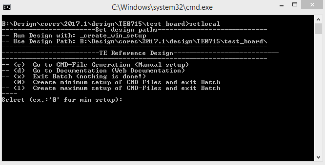
- Press 0 and enter for minimum setup
- (optional Win OS) Generate Virtual Drive or use short directory for the reference design (for example x:\<design name>)
- Create Project
- Select correct device and Xilinx install path on "design_basic_settings.cmd" and create Vivado project with "vivado_create_project_guimode.cmd"
Note: Select correct one, see TE Board Part Files
- Select correct device and Xilinx install path on "design_basic_settings.cmd" and create Vivado project with "vivado_create_project_guimode.cmd"
- Create HDF and export to prebuilt folder
- Run on Vivado TCL: TE::hw_build_design -export_prebuilt
Note: Script generate design and export files into \prebuilt\hardware\<short dir>. Use GUI is the same, except file export to prebuilt folder
- Run on Vivado TCL: TE::hw_build_design -export_prebuilt
- Create Linux (uboot.elf and image.ub) with exported HDF
- HDF is exported to "prebuilt\hardware\<short name>"
Note: HW Export from Vivado GUI create another path as default workspace. - Create Linux images on VM, see PetaLinux KICKstart
- Use TE Template from /os/petalinux
Note: run init_config.sh before you start petalinux config. This will set correct temporary path variable.
- Use TE Template from /os/petalinux
- HDF is exported to "prebuilt\hardware\<short name>"
- Add Linux files (uboot.elf and image.ub) to prebuilt folder
- "prebuilt\os\petalinux\default" or "prebuilt\os\petalinux\<short name>"
Notes: Scripts select "prebuilt\os\petalinux\<short name>", if exist, otherwise "prebuilt\os\petalinux\default"
- "prebuilt\os\petalinux\default" or "prebuilt\os\petalinux\<short name>"
- Generate Programming Files with HSI/SDK
- Run on Vivado TCL: TE::sw_run_hsi
Note: Scripts generate applications and bootable files, which are defined in "sw_lib\apps_list.csv" - (alternative) Start SDK with Vivado GUI or start with TE Scripts on Vivado TCL: TE::sw_run_sdk
Note: See SDK Projects
- Run on Vivado TCL: TE::sw_run_hsi
Launch
| Page properties | ||||
|---|---|---|---|---|
| ||||
Note:
|
| Note |
|---|
Check Module and Carrier TRMs for proper HW configuration before you try any design. Reference Design is also available with |
Additional Sources
...
Prebuilt
| HTML |
|---|
<!--

<table width="100%">
<tr> <th>File                                 </th> <th>File-Extension</th>  <th>Description                                                                              </th> </tr>
<tr> <td>BIF-File                             </td> <td>*.bif         </td>  <td>File with description to generate Bin-File                                               </td> </tr>
<tr> <td>BIN-File                             </td> <td>*.bin         </td>  <td>Flash Configuration File with Boot-Image (Zynq-FPGAs)                                    </td> </tr>
<tr> <td>BIT-File                             </td> <td>*.bit         </td>  <td>FPGA Configuration File                                                                  </td> </tr>
<tr> <td>DebugProbes-File                     </td> <td>*.ltx         </td>  <td>Definition File for Vivado/Vivado Labtools Debugging Interface                           </td> </tr>
<tr> <td>Debian SD-Image                      </td> <td>*.img         </td>  <td>Debian Image for SD-Card                                                                </td> </tr>
<tr> <td>Diverse Reports                      </td> <td>  ---         </td>  <td>Report files in different formats                                                        </td> </tr>
<tr> <td>Hardware-Platform-Specification-Files</td> <td>*.hdf         </td>  <td>Exported Vivado Hardware Specification for SDK/HSI                                       </td> </tr>
<tr> <td>LabTools Project-File                </td> <td>*.lpr         </td>  <td>Vivado Labtools Project File                                                             </td> </tr>
<tr> <td>MCS-File                             </td> <td>*.mcs         </td>  <td>Flash Configuration File with Boot-Image (MicroBlaze or FPGA part only)                  </td> </tr>
<tr> <td>MMI-File                             </td> <td>*.mmi         </td>  <td>File with BRAM-Location to generate MCS or BIT-File with *.elf content (MicroBlaze only) </td> </tr>
<tr> <td>OS-Image                             </td> <td>*.ub          </td>  <td>Image with Linux Kernel (On Petalinux optional with Devicetree and RAM-Disk)             </td> </tr>
<tr> <td>Software-Application-File            </td> <td>*.elf         </td>  <td>Software Application for Zynq or MicroBlaze Processor Systems                            </td> </tr>
<tr> <td>SREC-File                            </td> <td>*.srec        </td>  <td>Converted Software Application for MicroBlaze Processor Systems                          </td> </tr>
</table>
-->
|
Only on ZIP file with Prebuilt content.
...
File
...
File-Extension
...
Description
...
BIF-File
...
*.bif
...
File with description to generate Bin-File
...
BIN-File
...
*.bin
...
Flash Configuration File with Boot-Image (Zynq-FPGAs)
...
BIT-File
...
*.bit
...
FPGA (PL Part) Configuration File
...
DebugProbes-File
...
*.ltx
...
Definition File for Vivado/Vivado Labtools Debugging Interface
...
Diverse Reports
...
---
...
Report files in different formats
...
Hardware-Platform-Specification-Files
...
*.hdf
...
Exported Vivado Hardware Specification for SDK/HSI and PetaLinux
...
LabTools Project-File
...
*.lpr
...
Vivado Labtools Project File
...
OS-Image
...
*.ub
...
Image with Linux Kernel (On Petalinux optional with Devicetree and RAM-Disk)
...
Software-Application-File
...
*.elf
...
Software Application for Zynq or MicroBlaze Processor Systems
Download
Reference Design is only usable with the specified Vivado/SDK/PetaLinux/SDx version. Do never use different Versions of Xilinx Software for the same Project.
| HTML |
|---|
<!--
Add correct path:https://shop.trenz-electronic.de/en/Download/?path=Trenz_Electronic/TE0803/Reference_Design/2017.1/Starterkit
--> |
Reference Design is available on:
Design Flow
| HTML |
|---|
<!--
Basic Design Steps
Add/ Remove project specific
--> |
| Note |
|---|
Reference Design is available with and without prebuilt files. It's recommended to use TE prebuilt files for first lunch. |
Trenz Electronic provides a tcl based built environment based on Xilinx Design Flow.
See also:
TE0715-0x-30-xx only: HP IO Banks max power supply voltage is 1.8V. |
Programming
Xilinx documentation for programming and debugging: Vivado/SDK/SDSoC
...
The Trenz Electronic FPGA Reference Designs are TCL-script based project. Command files for execution will be generated with "_create_win_setup.cmd" on Windows OS and "_create_linux_setup.sh" on Linux OS.
TE Scripts are only needed to generate the vivado project, all other additional steps are optional and can also executed by Xilinx Vivado/SDK GUI. For currently Scripts limitations on Win and Linux OS see: Project Delivery Currently limitations of functionality
...
- Select correct device and Xilinx install path on "design_basic_settings.cmd" and create Vivado project with "vivado_create_project_guimode.cmd"
Note: Select correct one, see TE Board Part Files
...
- Run on Vivado TCL: TE::hw_build_design -export_prebuilt
Note: Script generate design and export files into \prebuilt\hardware\<short dir>. Use GUI is the same, except file export to prebuilt folder
...
- HDF is exported to "prebuilt\hardware\<short name>"
Note: HW Export from Vivado GUI create another path as default workspace. - Create Linux images on VM, see PetaLinux KICKstart
- Use TE Template from /os/petalinux
Note: run init_config.sh before you start petalinux config. This will set correct temporary path variable.
- Use TE Template from /os/petalinux
...
- "prebuilt\os\petalinux\default" or "prebuilt\os\petalinux\<short name>"
Notes: Scripts select "prebuilt\os\petalinux\<short name>", if exist, otherwise "prebuilt\os\petalinux\default"
-Xilinx Software Programming and Debugging
QSPI
Optional for Boot.bin on QSPI Flash and image.ub on SD.
- Connect JTAG and power on carrier with module
- Open Vivado Project with "vivado_open_existing_project_guimode.cmd" or if not created, create with "vivado_create_project_guimode.cmd"
- Type on Vivado TCL Console: TE::pr_program_flash_binfile -swapp u-boot
Note: To program with SDK/Vivado GUI, use special FSBL (zynq_fsbl_flash) on setup
optional "TE::pr_program_flash_binfile -swapp hello_te0715" possible - Copy image.ub on SD-Card
- Insert SD-Card
SD
- Copy image.ub and Boot.bin on SD-Card.
- For correct prebuilt file location, see <design_name>/prebuilt/readme_file_location.txt
- Set Boot Mode to SD-Boot.
- Depends on Carrier, see carrier TRM.
- Insert SD-Card in SD-Slot.
JTAG
Not used on this Example.
Usage
- Prepare HW like described on section Programming
- Connect UART USB (most cases same as JTAG)
- Select SD Card as Boot Mode (or QSPI - depending on step 1)
Note: See TRM of the Carrier, which is used. - Power On PCB
Note: 1. Zynq Boot ROM loads FSBL from SD into OCM, 2. FSBL loads U-boot from SD into DDR, 3. U-boot load Linux from SD into DDR
Linux
- Open Serial Console (e.g. putty)
- Speed: 115200
- COM Port: Win OS, see device manager, Linux OS see dmesg |grep tty (UART is *USB1)
- Linux Console:
Note: Wait until Linux boot finished For Linux Login use:- User Name: root
- Password: root
- You can use Linux shell now.
- I2C 1 Bus type: i2cdetect -y -r 1
- RTC check: dmesg | grep rtc
- ETH0 works with udhcpc
Vivado HW Manager
| Page properties | ||||
|---|---|---|---|---|
| ||||
Note:
|
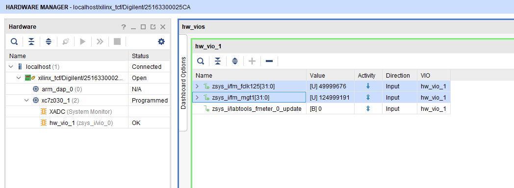
CLK Counters:
- Open Vivado HW-Manager and add VIO signal to dashboard (*.ltx located on prebuilt folder).
- Set radix from VIO signals to unsigned integer.
Note: Frequency Counter is inaccurate and displayed unit is Hz - MGT CLK is configured to 125MHz by default, FCLK is not configured by default (optional possible over FSBL, see FSBL description).
- Set radix from VIO signals to unsigned integer.
| Scroll Title | ||||
|---|---|---|---|---|
| ||||
 |
System Design - Vivado
| Page properties | ||||
|---|---|---|---|---|
| ||||
Note:
|
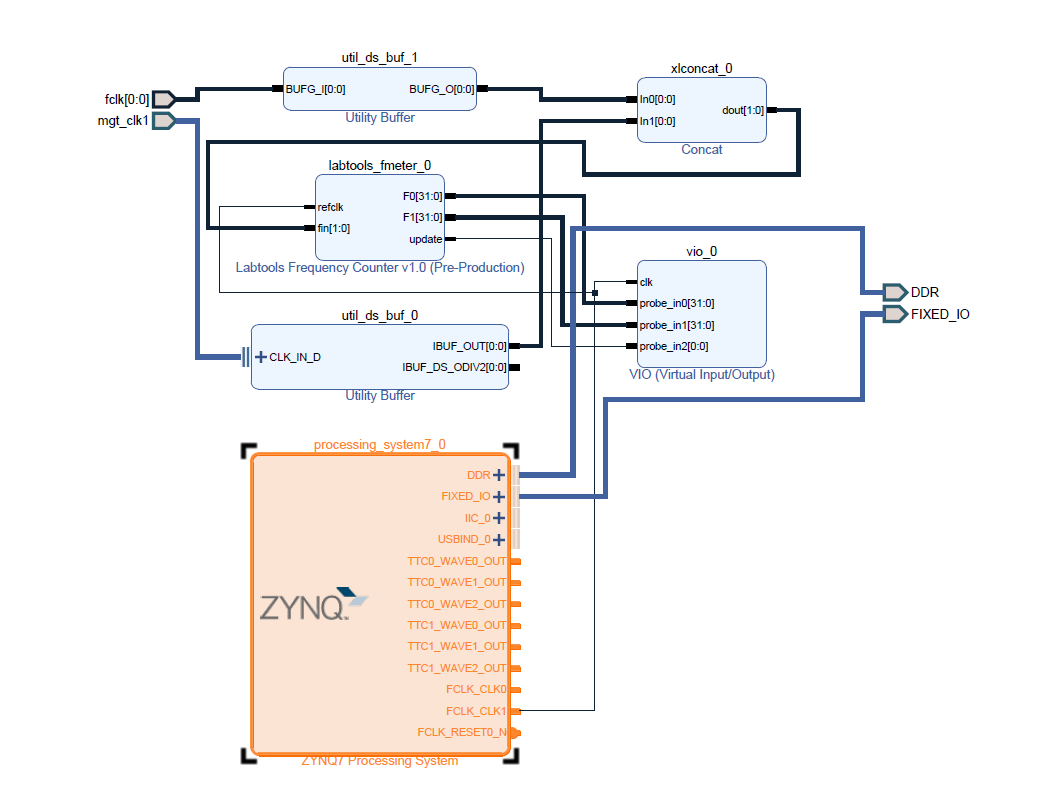
Block Design
| Scroll Title | ||||
|---|---|---|---|---|
| ||||
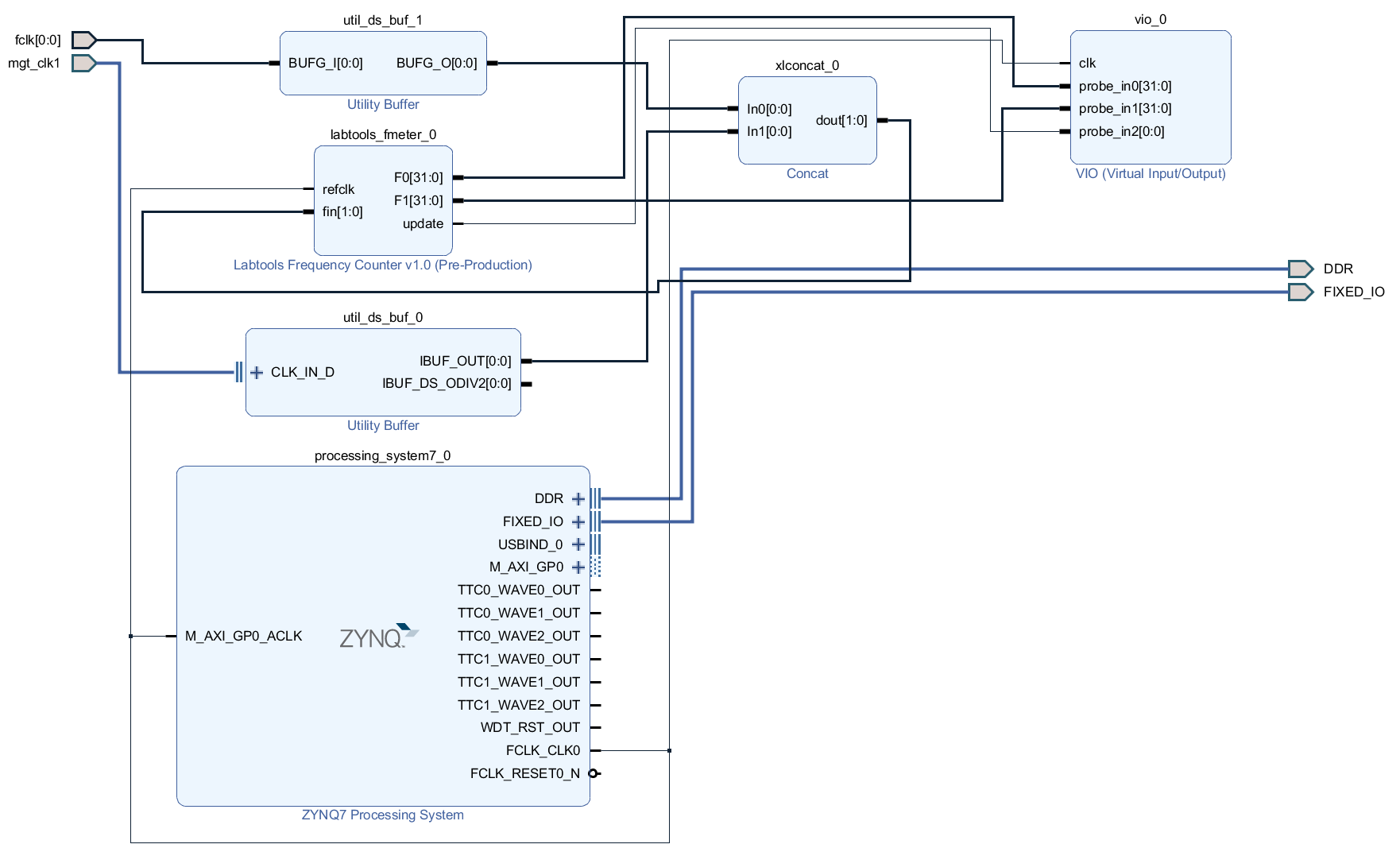 |
PS Interfaces
| Page properties | ||||
|---|---|---|---|---|
| ||||
Note:
|
Activated interfaces:
| Scroll Title | ||||||||||||||||||||||||||||||||||||||||||
|---|---|---|---|---|---|---|---|---|---|---|---|---|---|---|---|---|---|---|---|---|---|---|---|---|---|---|---|---|---|---|---|---|---|---|---|---|---|---|---|---|---|---|
| ||||||||||||||||||||||||||||||||||||||||||
|
Constrains
Basic module constrains
| Code Block | ||||
|---|---|---|---|---|
| ||||
set_property BITSTREAM.GENERAL.COMPRESS TRUE [current_design]
set_property CONFIG_VOLTAGE 3.3 [current_design]
set_property CFGBVS VCCO [current_design]

set_property BITSTREAM.CONFIG.USR_ACCESS TIMESTAMP [current_design] |
| Code Block | ||||
|---|---|---|---|---|
| ||||
set_property BITSTREAM.CONFIG.UNUSEDPIN PULLNONE [current_design] |
Design specific constrain
| Code Block | ||||
|---|---|---|---|---|
| ||||
set_property PACKAGE_PIN K2 [get_ports {fclk[0]}]
set_property IOSTANDARD LVCMOS18 [get_ports {fclk[0]}]
set_property CLOCK_DEDICATED_ROUTE FALSE [get_nets fclk_IBUF[0]] |
| Code Block | ||||
|---|---|---|---|---|
| ||||
# for fmeter only
set_false_path -from [get_clocks clk_fpga_0] -to [get_clocks {zsys_i/util_ds_buf_0/U0/IBUF_OUT[0]}]
set_false_path -from [get_clocks {zsys_i/util_ds_buf_0/U0/IBUF_OUT[0]}] -to [get_clocks clk_fpga_0]
set_false_path -from [get_clocks clk_fpga_0] -to [get_clocks {zsys_i/util_ds_buf_1/U0/BUFG_O[0]}] |
Software Design - SDK/HSI
| Page properties | ||||
|---|---|---|---|---|
| ||||
Note:
|
For SDK project creation, follow instructions from:
Application
Template location: ./sw_lib/sw_apps/
zynq_fsbl
TE modified 2018.2 FSBL
Changes:
- Si5338 Configuration
- see main.c, fsbl_hooks.c (d/remove define RECONFIGURE_SI5338 to enable PLL programming with given register_map.h setup (default activate))
- Add register_map.h, si5338.c, si5338.h
zynq_fsbl_flash
TE modified 2018.2 FSBL
Changes:
- Set FSBL Boot Mode to JTAG
- Disable Memory initialisation
hello_te0715
Hello TE0715 is a Xilinx Hello World example as endless loop instead of one console output.
u-boot
U-Boot.elf is generated with PetaLinux. SDK/HSI is used to generate Boot.bin.
Software Design - PetaLinux
| HTML |
|---|
<!--
- optional chapter, if petalinux is used
- Add changes from default petalinux project
--> |
For PetaLinux installation and project creation, follow instructions from:
Config
No changes.
U-Boot
No changes.
Device Tree
| Code Block | ||
|---|---|---|
| ||
/include/ "system-conf.dtsi"
/ {
};


/* default */

/* ETH PHY */
&gem0 {

    status = "okay";
        ethernet_phy0: ethernet-phy@0 {
        compatible = "marvell,88e1510";
        device_type = "ethernet-phy";
                reg = <0>;
    };
};


/* USB PHY */
/{
    usb_phy0: usb_phy@0 {
compatible = "ulpi-phy |
...
Launch
| HTML |
|---|
<!--
Description of Block Design, Constrains...
BD Pictures from Export...
--> |
| Note |
|---|
Check Module and Carrier TRMs for proper HW configuration before you try any design. Reference Design is also available with prebuilt files. It's recommended to use TE prebuilt files for first lunch. TE0715-0x-30-xx only: HP IO Banks max power supply voltage is 1.8V. |
Programming
Xilinx documentation for programming and debugging: Vivado/SDK/SDSoC-Xilinx Software Programming and Debugging
QSPI
Optional for Boot.bin on QSPI Flash and image.ub on SD.
- Connect JTAG and power on carrier with module
- Open Vivado Project with "vivado_open_existing_project_guimode.cmd" or if not created, create with "vivado_create_project_guimode.cmd"
- Type on Vivado TCL Console: TE::pr_program_flash_binfile -swapp u-boot
Note: To program with SDK/Vivado GUI, use special FSBL (zynq_fsbl_flash) on setup - Copy image.ub on SD-Card
- Insert SD-Card
SD
- Copy image.ub and Boot.bin on SD-Card.
- For correct prebuilt file location, see <design_name>/prebuilt/readme_file_location.txt
- Set Boot Mode to SD-Boot.
- Depends on Carrier, see carrier TRM.
- Insert SD-Card in SD-Slot.
JTAG
Not used on this Example.
Usage
- Prepare HW like described on section Programming
- Connect UART USB (most cases same as JTAG)
- Select SD Card as Boot Mode (or QSPI - depending on step 1)
Note: See TRM of the Carrier, which is used. - Power On PCB
Note: 1. Zynq Boot ROM loads FSBL from SD into OCM, 2. FSBL loads U-boot from SD into DDR, 3. U-boot load Linux from SD into DDR
Linux
- Open Serial Console (e.g. putty)
- Speed: 115200
- COM Port: Win OS, see device manager, Linux OS see dmesg |grep tty (UART is *USB1)
- Linux Console:
Note: Wait until Linux boot finished For Linux Login use:- User Name: root
- Password: root
- You can use Linux shell now.
- I2C 1 Bus type: i2cdetect -y -r 1
- RTC check: dmesg | grep rtc
- ETH0 works with udhcpc
Vivado HW Manager
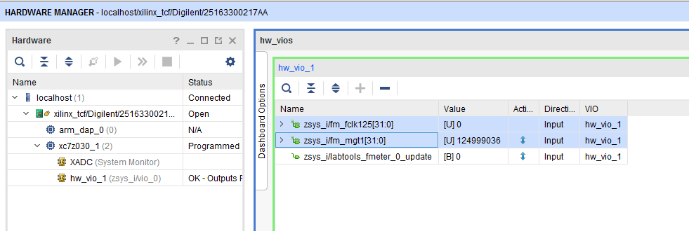
MGT Reference CLK Counter:
- Open Vivado HW-Manager and add VIO signal to dashboard (*.ltx located on prebuilt folder).
- Set radix from VIO signals to unsigned integer.
Note: Frequency Counter is inaccurate and displayed unit is Hz
- Set radix from VIO signals to unsigned integer.
MGT CLK is configured to 125MHz by default, FCLK is not configured by default (optional possible see FSBL description).
System Design - Vivado
| HTML |
|---|
<!--
Description of Block Design, Constrains...
BD Pictures from Export...
--> |
Block Design
PS Interfaces
Activated interfaces:
...
Constrains
Basic module constrains
| Code Block | ||||
|---|---|---|---|---|
| ||||
set_property BITSTREAM.GENERAL.COMPRESS TRUE [current_design]
set_property CONFIG_VOLTAGE 3.3 [current_design]
set_property CFGBVS VCCO [current_design]

set_property BITSTREAM.CONFIG.USR_ACCESS TIMESTAMP [current_design] |
| Code Block | ||||
|---|---|---|---|---|
| ||||
set_property BITSTREAM.CONFIG.UNUSEDPIN PULLNONE [current_design] |
Design specific constrain
| Code Block | ||||
|---|---|---|---|---|
| ||||
set_property PACKAGE_PIN K2 [get_ports {fclk[0]}]
set_property IOSTANDARD LVCMOS18 [get_ports {fclk[0]}]
set_property CLOCK_DEDICATED_ROUTE FALSE [get_nets fclk_IBUF[0]] |
Software Design - SDK/HSI
| HTML |
|---|
<!--
optional chapter
separate sections for different apps
--> |
For SDK project creation, follow instructions from:
Application
zynq_fsbl
TE modified 2017.4 FSBL
Changes:
- Si5338 Configuration see fsbl_hooks.c
add define RECONFIGURE_SI5338 to enable PLL programming with given register_map.h setup - Add register_map.h, si5338.c, si5338.h
zynq_fsbl_flash
TE modified 2017.4 FSBL
Changes:
- Set FSBL Boot Mode to JTAG
- Disable Memory initialisation
U-Boot
U-Boot.elf is generated with PetaLinux. SDK/HSI is used to generate Boot.bin.
Software Design - PetaLinux
| HTML |
|---|
<!--
- optional chapter, if petalinux is used
- Add changes from default petalinux project
--> |
For PetaLinux installation and project creation, follow instructions from:
Config
No changes.
U-Boot
No changes.
Device Tree
| Code Block | ||
|---|---|---|
| ||
/include/ "system-conf.dtsi" / { }; /* default */ /* ETH PHY */ &gem0 { status = "okay"; ethernet_phy0: ethernet-phy@0 {//compatible = "usb-nop-xceiv"; compatible#phy-cells = "marvell,88e1510"<0>; device_typereg = "ethernet-phy" <0xe0002000 0x1000>; view-port = <0x0170>; reg = <0>drv-vbus; }; }; /* USB PHY */ /&usb0 { usb_phy0: usb_phy@0 { compatibledr_mode = "ulpi-phyhost"; //compatibledr_mode = "usb-nop-xceivperipheral"; #phy-cellsusb-phy = <0>; reg = <0xe0002000 0x1000>;<&usb_phy0>; }; /* I2C */ // i2c PLL: 0x70, i2c eeprom: 0x50 &i2c1 { rtc@6F { view-port = <0x0170>; // Real drv-vbus;Time Clock }; }; &usb0 { compatible dr_mode = "hostisl12022"; //dr_mode reg = "peripheral"<0x6F>; usb-phy = <&usb_phy0>; }; /* I2C */ // i2c PLL: 0x70, i2c eeprom: 0x50 &i2c1 { rtc@6F { // Real Time Clock compatible = "isl12022"; reg = <0x6F>; }; }; |
Kernel
Activate:
- RTC_DRV_ISL12022
Rootfs
Activate:
- i2c-tools
Applications
startup
Script App to load init.sh from SD Card if available.
See: \os\petalinux\project-spec\meta-user\recipes-apps\startup\files
Additional Software
| HTML |
|---|
<!--
Add Description for other Software, for example SI CLK Builder ...
--> |
SI5338
Download ClockBuilder Desktop for SI5338
- Install and start ClockBuilder
- Select SI5338
- Options → Open register map file
Note: File location <design name>/misc/Si5338/RegisterMap.txt - Modify settings
- Options → save C code header files
- Replace Header files from FSBL template with generated file
Appx. A: Change History and Legal Notices
Document Change History
To get content of older revision got to "Change History" of this page and select older document revision number.
| HTML |
|---|
<!--
Generate new entry:
1:add new row below first
2:Copy Page Information Macro(date+user) Preview, Page Information Macro Preview
3.Update Metadate =Page Information Macro Preview+1
--> |
...
- New assembly variant
};

};
|
Kernel
Activate:
- RTC_DRV_ISL12022
Rootfs
Activate:
- i2c-tools
Applications
startup
Script App to load init.sh from SD Card if available.
See: \os\petalinux\project-spec\meta-user\recipes-apps\startup\files
Additional Software
| Page properties | ||||
|---|---|---|---|---|
| ||||
| Note: |
SI5338
File location <design name>/misc/Si5338/RegisterMap.txt
General documentation how you work with these project will be available on Si5338
Appx. A: Change History and Legal Notices
Document Change History
To get content of older revision got to "Change History" of this page and select older document revision number.
| Page properties | ||||
|---|---|---|---|---|
| ||||
|
| Scroll Title | |||||||||||||||||||||||||||||||||||||||||||||||||||||||||||||
|---|---|---|---|---|---|---|---|---|---|---|---|---|---|---|---|---|---|---|---|---|---|---|---|---|---|---|---|---|---|---|---|---|---|---|---|---|---|---|---|---|---|---|---|---|---|---|---|---|---|---|---|---|---|---|---|---|---|---|---|---|---|
| |||||||||||||||||||||||||||||||||||||||||||||||||||||||||||||
|
...
|
...
|
...
|
...
...
|
...
|
...
Legal Notices
| Include Page | ||||
|---|---|---|---|---|
|
...
Overview
Content Tools