...
| Scroll Title |
|---|
| anchor | Figure_OV_MC |
|---|
| title | TEBT0782 main components |
|---|
|
| Scroll Ignore |
|---|
| draw.io Diagram |
|---|
| border | false |
|---|
| viewerToolbar | true |
|---|
| |
|---|
| fitWindow | false |
|---|
| diagramDisplayName | |
|---|
| lbox | true |
|---|
| revision | 58 |
|---|
| diagramName | TEBT0782_OV_MC |
|---|
| simpleViewer | false |
|---|
| width | |
|---|
| links | auto |
|---|
| tbstyle | hidden |
|---|
| diagramWidth | 440 |
|---|
|
|
| Scroll Only |
|---|
|
|
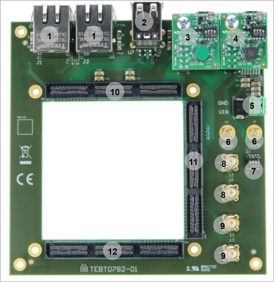
- RJ45 Transceivers, J1-J2
- USB A Stacked, U7
- XMOD JTAG/UART BaseAdapter, J7
- JTAG CPLD Adapter -J8
- 2 Line Common Mode Choke, J10
- Non-isolated power jack (VIN), J9
- Non-isolated power jack (GND), J11
- DIP Switch, S1
- SMA Coxial Connectors, J3...J6
- Board to Board Connectors, JB1...JB3
...
JTAGs access to the TEBT0782 SoM are available through B2B connector JB3. JTAG access to the LCMXO2-1200HC System Controller CPLD is provided through B2B connector J3.
Pin J3-136 'JTAGENB' of B2B connector J3 is used to access the JTAG interface of the SC CPLD. Set it high using DIP Switch S1-A in order to program the System Controller CPLD via JTAG interaface.
| Scroll Title |
|---|
| anchor | Table_SIP_JTG |
|---|
| title | JTAG pins connection |
|---|
|
| Scroll Table Layout |
|---|
| orientation | portrait |
|---|
| sortDirection | ASC |
|---|
| repeatTableHeaders | default |
|---|
| style | |
|---|
| widths | |
|---|
| sortByColumn | 1 |
|---|
| sortEnabled | false |
|---|
| cellHighlighting | true |
|---|
|
| TE0790 Base | JTAG Signal | B2B Connector | Notes |
|---|
| J8 | TMS | JB3C-142 | CPLD JTAG | | TDI | JB3C-147 | CPLD JTAG | | TDO | JB3C-148 | CPLD JTAG | | TCK | JB3C-141 | CPLD JTAG |
|
| Scroll Title |
|---|
| anchor | Table_SIP_JTG |
|---|
| title | JTAG pins connection |
|---|
|
| Scroll Table Layout |
|---|
| orientation | portrait |
|---|
| sortDirection | ASC |
|---|
| repeatTableHeaders | default |
|---|
| style | |
|---|
| widths | |
|---|
| sortByColumn | 1 |
|---|
| sortEnabled | false |
|---|
| cellHighlighting | true |
|---|
|
JTAG Signal | B2B Connector | Notes | J8 |
|---|
| M_TMS | JB3B-182 | JTAG | | M_TDI | JB3B-187 | JTAG | | M_TDO | JB3B-188 | JTAG | | M_TCK | JB3B-181 | JTAG |
|
UART
| Scroll Title |
|---|
| anchor | Table_SIP_UART |
|---|
| title | UART Pins |
|---|
|
| Scroll Table Layout |
|---|
| orientation | portrait |
|---|
| sortDirection | ASC |
|---|
| repeatTableHeaders | default |
|---|
| style | |
|---|
| widths | |
|---|
| sortByColumn | 1 |
|---|
| sortEnabled | false |
|---|
| cellHighlighting | true |
|---|
|
Signal State | B2B | Notes |
|---|
| XMOD_A | JB3C- 129 | Used as UART TX line | XMOD_B | JB3C- 135 | Used as UART RX line |
|
...
| Scroll Title |
|---|
| anchor | Table_OBP_DIP |
|---|
| title | DIP Switch Connections |
|---|
|
| Scroll Table Layout |
|---|
| orientation | portrait |
|---|
| sortDirection | ASC |
|---|
| repeatTableHeaders | default |
|---|
| style | |
|---|
| widths | |
|---|
| sortByColumn | 1 |
|---|
| sortEnabled | false |
|---|
| cellHighlighting | true |
|---|
|
| Switch | Connected to | B2B | Notes |
|---|
| S1-A | JTABENB | JB3C-136 |
| | S1-B...D | - | -No | functionalityNot connected |
|
Power and Power-On Sequence
...
Power supply with minimum current capability of 4 3 A for system startup is recommended.
...
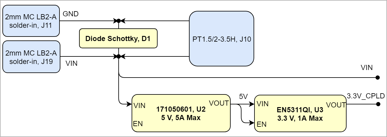
Power Distribution Dependencies
12V Power Supply (VIN) on J9/J11 (2 mm MC LB2-A solder-in) or on J10 (TE1.5/2-3.5H).
| Scroll Title |
|---|
| anchor | Figure_PWR_PD |
|---|
| title | Power Distribution |
|---|
|
| Scroll Ignore |
|---|
| scroll-pdf | false |
|---|
| scroll-office | true |
|---|
| scroll-chm | true |
|---|
| scroll-docbook | true |
|---|
| scroll-eclipsehelp | true |
|---|
| scroll-epub | true |
|---|
| scroll-html | true |
|---|
| | draw.io Diagram |
|---|
| border | false |
|---|
| viewerToolbar | true |
|---|
| |
|---|
| fitWindow | false |
|---|
| diagramDisplayName | |
|---|
| lbox | true |
|---|
| revision | 27 |
|---|
| diagramName | TEBT0784_PWR_PD |
|---|
| simpleViewer | false |
|---|
| width | |
|---|
| links | auto |
|---|
| tbstyle | hidden |
|---|
| diagramWidth | 641 |
|---|
|
|
|
| Scroll Only |
|---|

|
|
Power-On Sequence
| Scroll Title |
|---|
| anchor | Figure_PWR_PS |
|---|
| title | Power Sequency |
|---|
|
| Scroll Ignore |
|---|
| draw.io Diagram |
|---|
| border | false |
|---|
| viewerToolbar | true |
|---|
| |
|---|
| fitWindow | false |
|---|
| diagramDisplayName | |
|---|
| lbox | true |
|---|
| revision | 47 |
|---|
| diagramName | TEBT0782_PWR_PS |
|---|
| simpleViewer | false |
|---|
| width | |
|---|
| links | auto |
|---|
| tbstyle | hidden |
|---|
| diagramWidth | 641 |
|---|
|
|
| Scroll Only |
|---|
|
|
...
| Scroll Title |
|---|
| anchor | Table_PWR_PR |
|---|
| title | Module power rails. |
|---|
|
| Scroll Table Layout |
|---|
| orientation | portrait |
|---|
| sortDirection | ASC |
|---|
| repeatTableHeaders | default |
|---|
| style | |
|---|
| widths | |
|---|
| sortByColumn | 1 |
|---|
| sortEnabled | false |
|---|
| cellHighlighting | true |
|---|
|
| Power Rail Name | B2B JM1 Pin | B2B JM2 Pin | B2B JM3 Pin | VoltageDirection | Notes |
|---|
| VIN | 165, 166, 167, 168 | - | -12 V | Input/Output | Directly to module | | 3.3V_M | 99, 100, 111,112, 123, 124, 135, 136, 159, 160, 169, 170, 171, 172 | - | 99, 100, 159, 160 | 3.3 VOutput |
| | 3.3V_CPLD | 147,148 | - | -3.3 V | Output | Directly to module | | 1.8V_M | - | 99,100, 159, 160, 169, 170, 171, 172 | 124 | 1.8 VOutput |
|
|
Board to Board Connectors
...
| Scroll Title |
|---|
| anchor | Table_RH_HRH |
|---|
| title | Hardware Revision History |
|---|
|
| Scroll Table Layout |
|---|
| orientation | portrait |
|---|
| sortDirection | ASC |
|---|
| repeatTableHeaders | default |
|---|
| style | |
|---|
| widths | |
|---|
| sortByColumn | 1 |
|---|
| sortEnabled | false |
|---|
| cellHighlighting | true |
|---|
|
| Date | Revision | Changes | Documentation Link |
|---|
| 52016-11-201605 | 01 | - | REV01 |
|
Hardware revision number can be found on the PCB board together with the module model number separated by the dash.
...
| Include Page |
|---|
| IN:Legal Notices |
|---|
| IN:Legal Notices |
|---|
|
| draw.io Diagram |
|---|
| border | false |
|---|
| viewerToolbar | true |
|---|
| |
|---|
| fitWindow | false |
|---|
| diagramDisplayName | |
|---|
| lbox | true |
|---|
| revision | 7 |
|---|
| diagramName | TEBT0784_PWR_PD |
|---|
| simpleViewer | false |
|---|
| width | |
|---|
| links | auto |
|---|
| tbstyle | hidden |
|---|
| diagramWidth | 641 |
|---|
|