Page History
...
| Page properties | ||||
|---|---|---|---|---|
| ||||
Notes :
|
Key Features
| Page properties | ||||
|---|---|---|---|---|
| ||||
Note: Key Features' must be split into 6 main groups for modules and mainboards:
Key Features' must be split into 6 main groups for carrier:
|
...
| Scroll Title | ||||||||||||||||||||||||||||||||
|---|---|---|---|---|---|---|---|---|---|---|---|---|---|---|---|---|---|---|---|---|---|---|---|---|---|---|---|---|---|---|---|---|
| ||||||||||||||||||||||||||||||||
|
...
| Scroll Title | ||||||||||||||||||||||||||||||||||
|---|---|---|---|---|---|---|---|---|---|---|---|---|---|---|---|---|---|---|---|---|---|---|---|---|---|---|---|---|---|---|---|---|---|---|
| ||||||||||||||||||||||||||||||||||
|
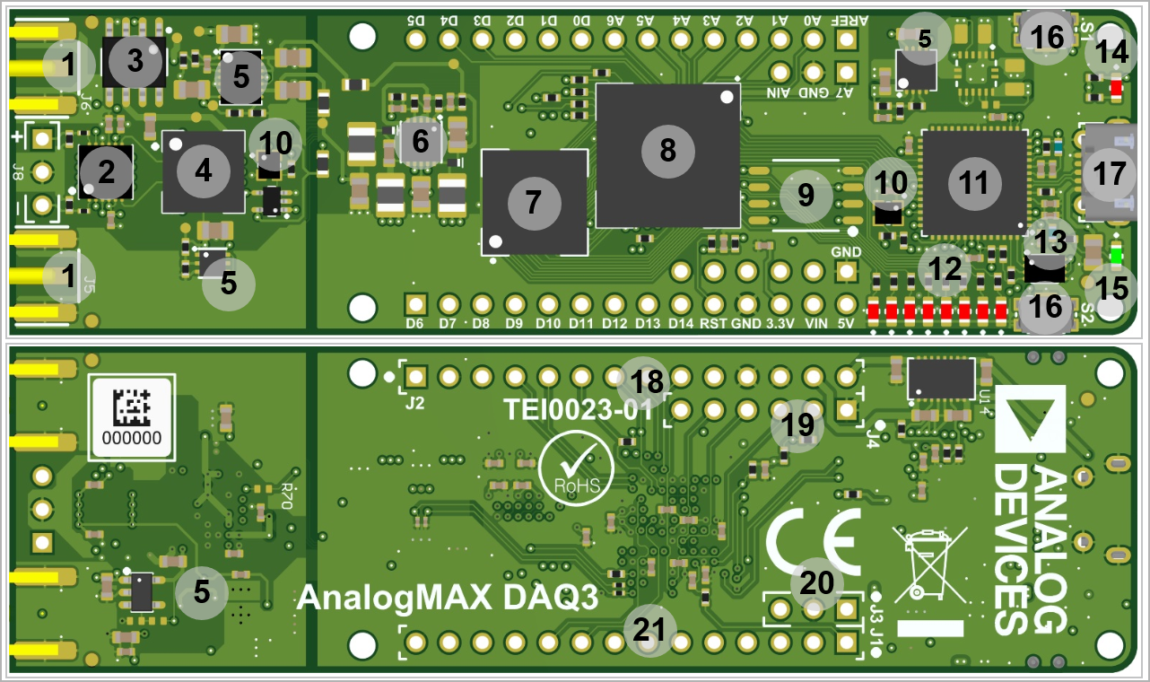
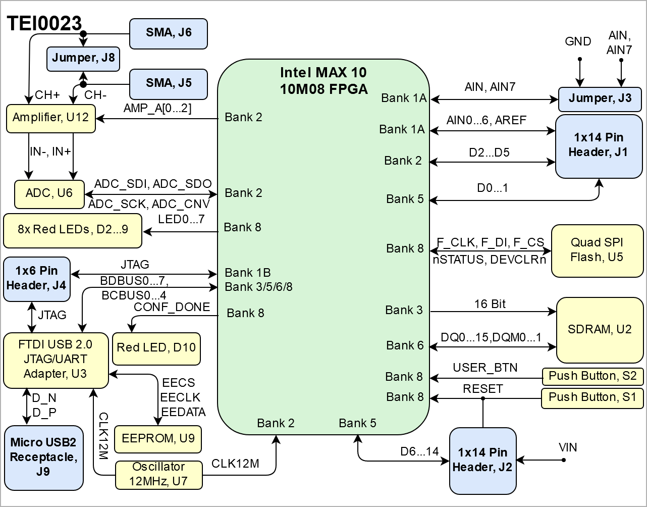
SMA Connector, J5...6
Amplifier, U12
Series Voltage Reference, U8
Analog to Digital Converter, U6
Voltage Regulator, U4 - U10 - U13 - U16
Switching Voltage Regulator, U11
SDRAM Memory, U2
- Intel® MAX 10, U1
SPI Flash Memory, U5
Oscillator, U7 - U19
FTDI USB2 to JTAG/UART Adapter, U3
User LEDs, D2...9
FTDI Configuration EEPROM, U9
Configuration/Status LED (Red) , D10
Power-On LED (Green), D1
Push Button, S1...2
Micro USB Connector, J9
1x14 Pin Header, J2 (Not assembled)
1x6 Pin Header, J4 (Not assembled)
1x4 Pin Header, J3 (Not assembled)
1x14 Pin Header, J1 (Not assembled)
...
Overview
Content Tools