The mode select pins M[2:0] define the configuration mode that the FPGA uses to load its bitstream. The table below shows the configuration modes supported by TE0320. The logic level applied to the mode pins is sampled on the rising edge of INIT_B, immediately after the FPGA completes initializing its internal configuration memory. See Xilinx UG332: Spartan-3 Generation Configuration User Guide for additional information on these signals.
configuration mode | M2 | M1 | M0 |
master SPI | 0 | 0 | 1 |
JTAG | 1 | 0 | 1 |
slave parallel (SelectMAP) | 1 | 1 | 0 |
slave serial | 1 | 1 | 1 |
Mode pin settings supported by TE0320.
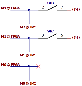
Configuration modes schematic
Xilinx Spartan-3 generation FPGAs have a dedicated four-wire IEEE 1149.1/1532 JTAG port that is always available any time the FPGA is powered and regardless of the mode pin settings. However, when the FPGA mode pins are set for JTAG mode (M[2:0] = <1:0:1>), the FPGA waits to be configured via the JTAG port after a power-on event or after PROG_B is pulsed Low. Selecting the JTAG mode simply disables the other configuration modes. No other pins are required as part of the configuration interface.
M0-M2 have Pull up resistors in FPGA.
- If S1B and S1C are off, then signals from B2B should be left float.
- If S1B and S1C are on, then mode can be set from B2B.
Never set Mx from B2B directly to one.
Never set M2 and M1 from B2B directly to a Power Supply or to a "logical" '1' (aka a digital port with output '1').
Without an interposing resistor, a shortcircuit between Power Supply and GND is possible.
Without an interposing resistor, a shortcircuit between the output of a digital port set to High ("1") and GND is possible. This could damage (or at least force the use of the overcurrent protection of) the digital port used.
The table below shows some options about setting mode pin M2 high or low.
M2 value | M2 @ S1B | M2 @ JM5 |
0 | ON | any |
0 | any | 0 |
1 | OFF | floating |
1 | OFF | 1 |
Mode pin M2 settings.
The table below shows some options about setting mode pin M1 high or low.
M1 value | M1 @ S1C | M1 @ JM5 |
0 | ON | any |
0 | any | 0 |
1 | OFF | floating |
1 | OFF | 1 |
Mode pin M1 settings.
The table below shows some options about setting mode pin M0 high or low.
M0 value | M0 @ JM5 |
|---|---|
0 | 0 |
1 | floating |
1 | 1 |
Mode pin M0 settings.
Overview
Content Tools