In this tutorial we are going to add a AXI GPIO IP to the Blockdesign and connect two external LEDs to the AXI GPIO IP Core. After generating the Bitstream we export the design to Vitis and control the LEDs with software(C/C++) running on the MicroBlaze. In the same way you can connect any other I/Os external or internal the Chip.
This tutorial is based on the the reference design of the TE0717 Board and Vitis 2021.2 was used.
- First open the prebuilt reference design with the "_create_win_setup.cmd" script and open the block design.
Add a second "AXI GPIO IP" from the IP catalog to the block design.
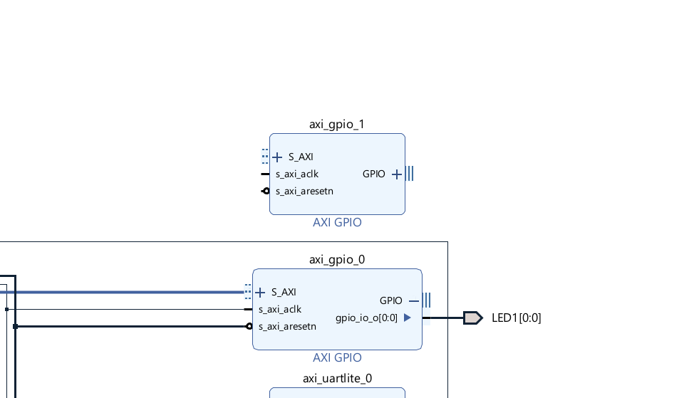 Figure 1: Adding AXI GPIO IP Core
Configure the IP by double-clicking on the IP. Make the changes and click "ok".
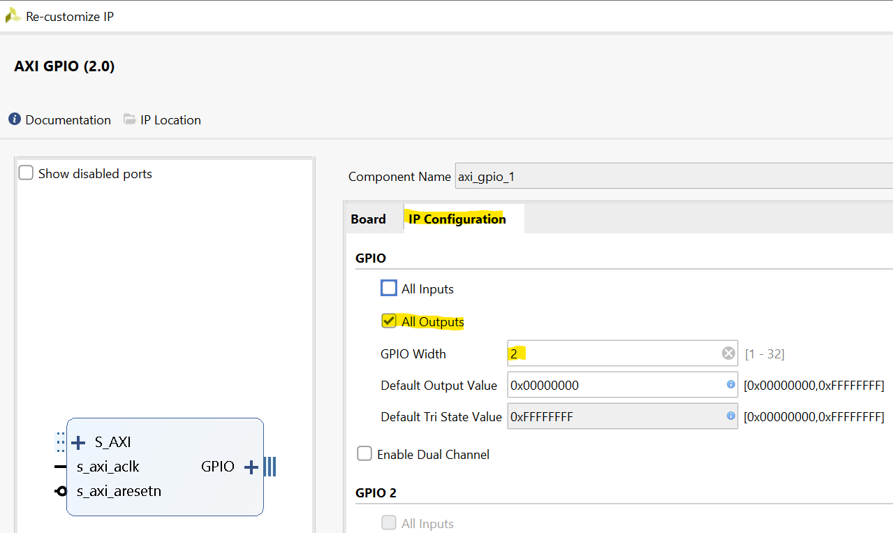 Figure 2: AXI GPIO IP Core Configuration
Right click on the port and choose "Make external" in the context menu
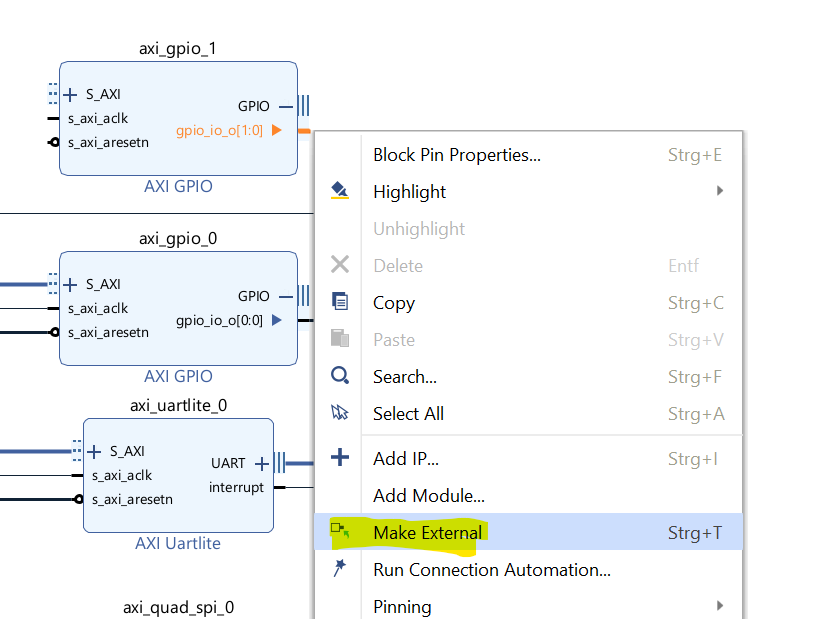 Figure 3: Make the AXI GPIO Ports external for the Carrier LEDs
Run the connection automation. The AXI GPIO IP Core gets connected to the MicroBlaze via the AXI Interface.
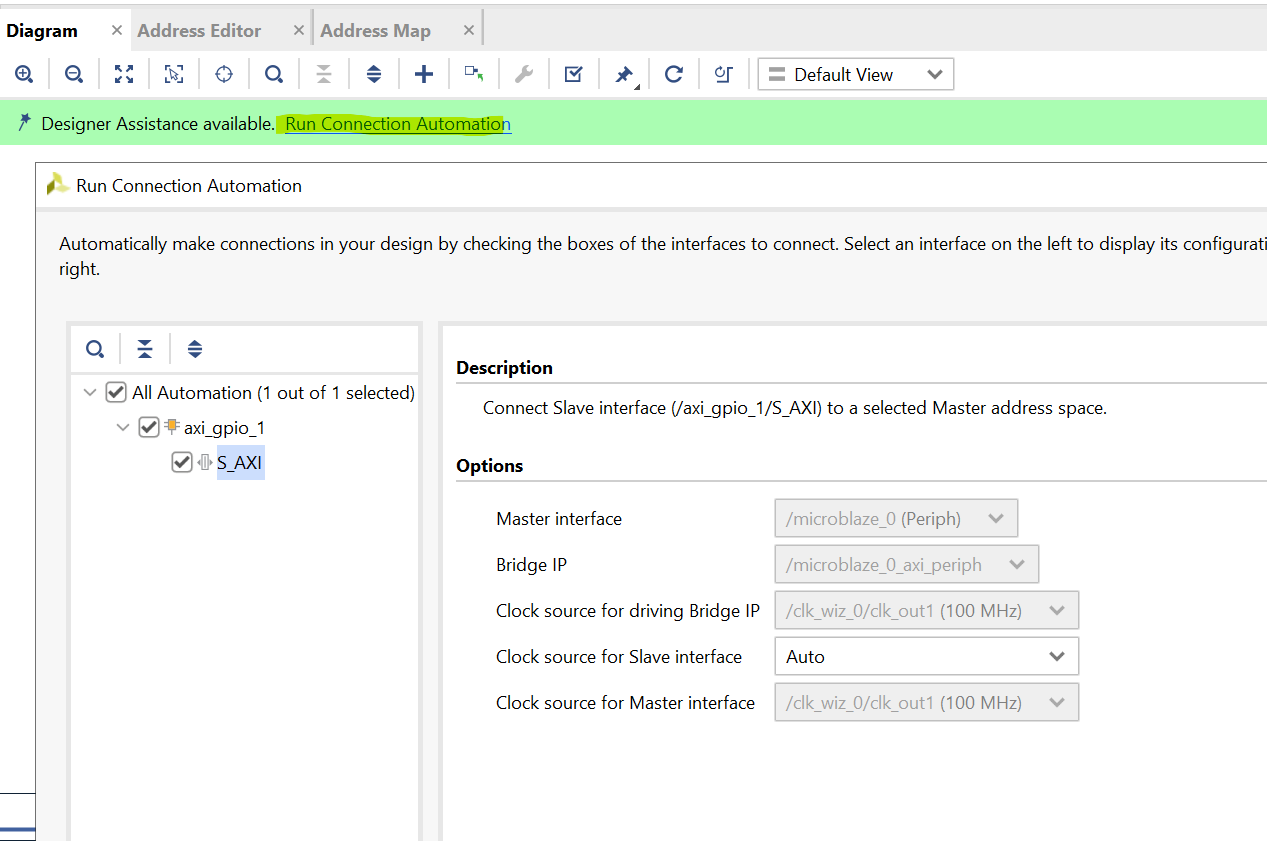 Figure 4: Run Connection Automation
Now the address mapping in the address editor should be set like:
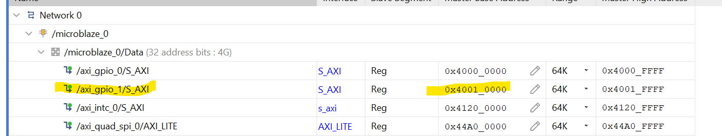 Figure 5: Address Editor - AXI GPIO 1
Next, the constraints for the two leds have to be set in the constraint file.
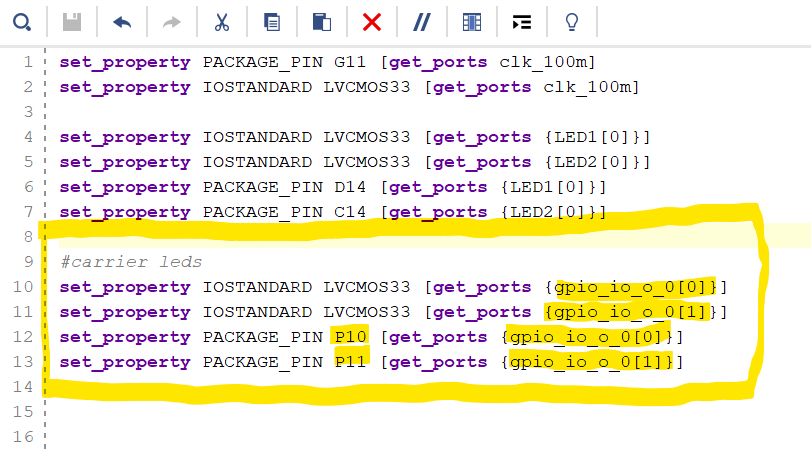 Figure 6: LEDs constraints
Now you are all set in Vivado and you can build the bitstream + export the project to Vitis with the following command in the TCL-console(only possible in the script-based reference design from trenz).
Manual steps would be to Generate the Bitstream and export the hardware platform.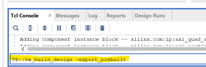 Figure 7: Build bitstream and export project
After that was successful you can test the functionality of the VIO Core by programming the FPGA and controlling the onBoard LED2.
Otherwise continue with Step 10.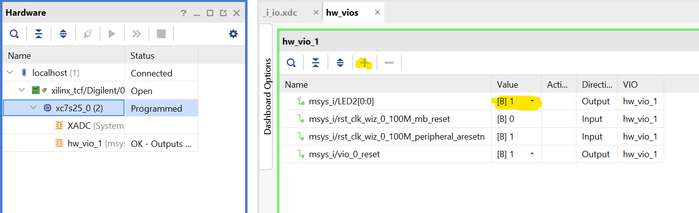 Figure 8: Program FPGA and control onboard LED through the VIO IP Core.
Now you can build the Vitis project with the provided C/C++-Applications with the following command.
Manual steps would be to Open Vitis(Tools → Launch Vitis IDE) and import the project from the project directory.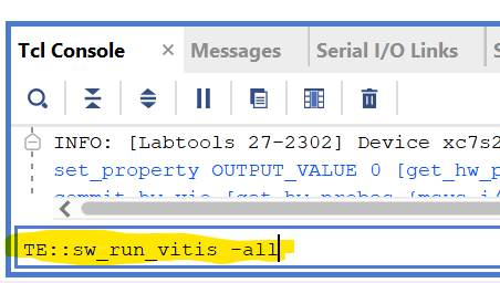 Figure 9: Build Vitis project with built vivado design
In Vitis open the hello_te0717 application:
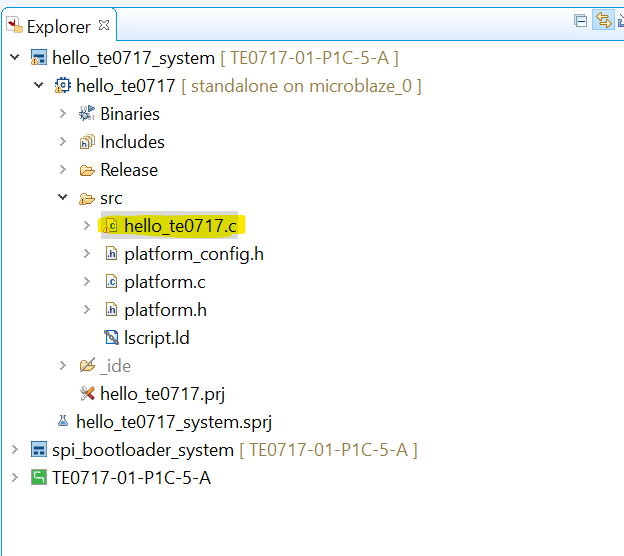 Figure 10: Vitis hello_te0717
Add the following lines of code to also make both of the LEDs blink:
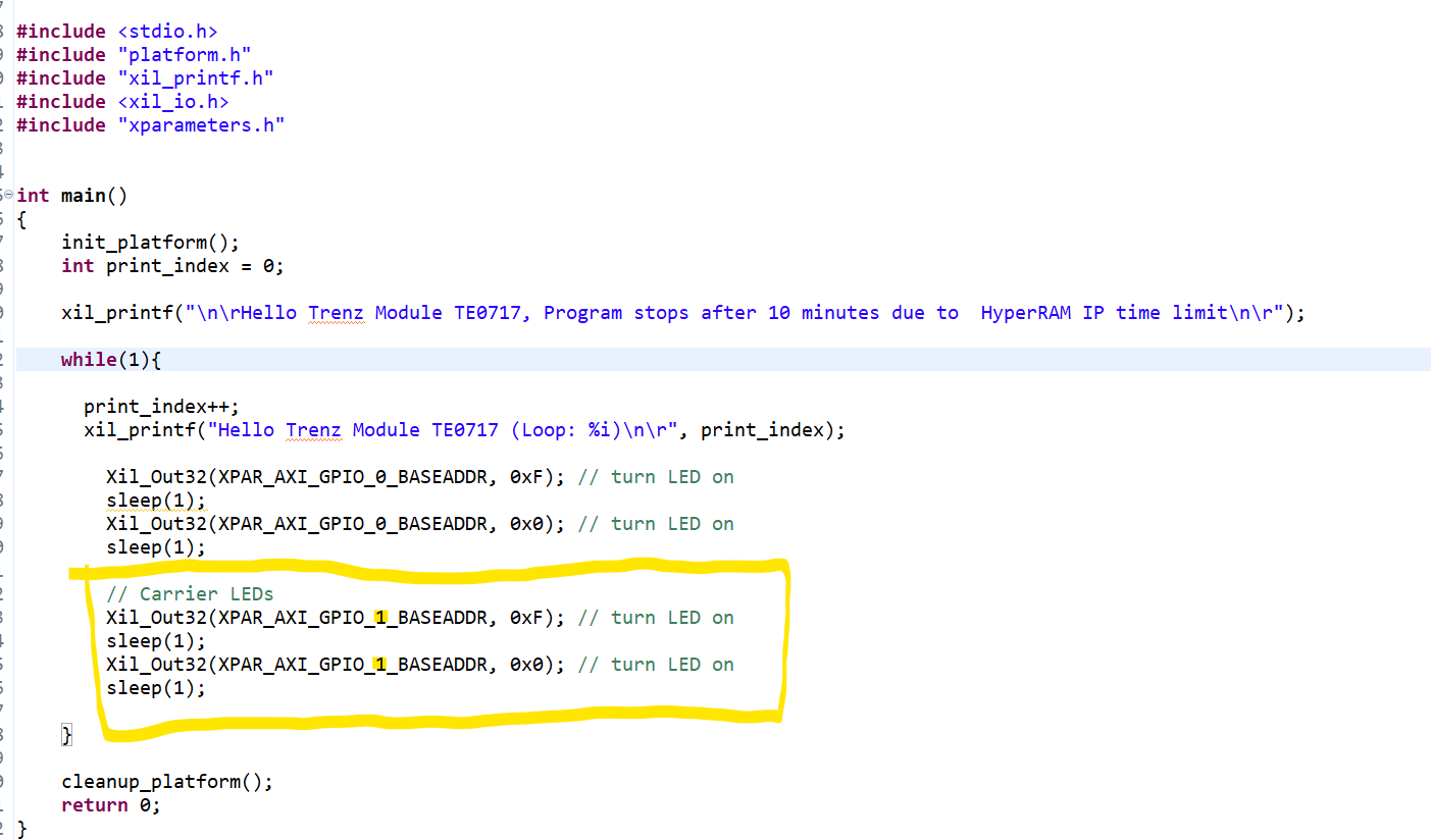 Figure 11: hello_te0717 adding code for controlling carrier LEDs
- Save and Build the project
Right-Click on the application and choose "Run Configuration"
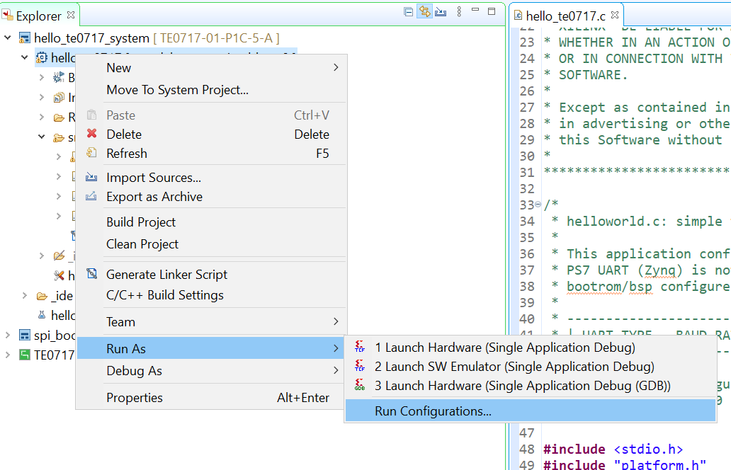 Figure 12: Run Configuration
Since we already programmed the FPGA, uncheck the following:
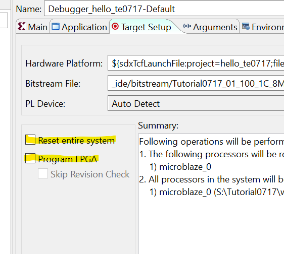 Figure 13: Run Configuration - Uncheck
- Click on Apply and Run to execute the program on the MicroBlaze. You Should now see the LEDs of the module and carrier blinking in sequence.
Also if you open up a serial connection to the board with a program like PuTTY, you should see output
Overview
Content Tools