Introduction
Electronic Drive Development Platform (EDDP) provides all necessary software and hardware components for development and evaluation of motor control applications. While those components (both software and hardware) can also be used separatly this manual describes EDDP usage with default reference hardware platform (EDDP Kit) only.
Hardware components/boards delivered in EDDP Kit are not intended to be used in finished products. All the software and hardware parts of the EDDP are intended for Developers evaluating Motor Control Applications with Xilinx FPGA and/or SoC Devices.
Requirements for Functional Test
It is possible to run the default control firmware and GUI to verify the that the hardware is functional.
Following items are required in addition to EDDP Kit:
- Micro-USB Cable for the USB console of the Controller Board.
- Ethernet-based LAN with a DHCP server.
- RJ45 ethernet Cable.
- Computer with web browser to access the Web UI.
- Card reader supporting micro-SD Cards.
- Access to internet (to download SD Card images).
In order to pass EMC radiatied emission (EN 55011) class B requirements option "Spread Spectrum" must be activated (standard setting).
Software version that was used in EMC test: (Visible in the GUI main scren) 2017-7-31 (SVN Tag 5745).
Requirements for Development
For development with SDSoC additonal items are required:
- All items listed under Requirements for Functional Test.
- Basic knowledge of Xilinx All Programmable FPGA and/or SoC devices, basic knowledge of Xilinx SDK and C/C++ programming in order to be able to adapt the firmware to your requirements.
- A PC capable of running Xilinx SDSoC 2017.1
- Valid Xilinx SDSoC License or Voucher.
For development with HLS additonal items are required:
- All items listed under Requirements for Functional Test.
- Basic knowledge of Xilinx All Programmable FPGA and/or SoC devices, basic knowledge of Xilinx SDK and C/C++ programming in order to be able to adapt the firmware to your requirements.
- A PC capable of running Xilinx Vivado 2017.1
Installation
Micro-SD is delivered without Linux images to avoid any issues related to US export control regulations.
Hardware Assembly
When delivered as full EDDP Kit several components are pre-assembled.
Motor Adapter Board
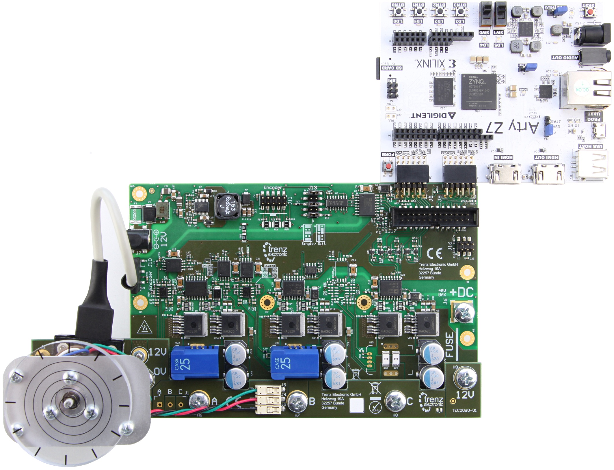
The default (Refence) Motor with Encoder is connected to the Driver Board using special "Adapter Board" (TEC0060). In the EDDP Kit the Motor is pre-assembled:
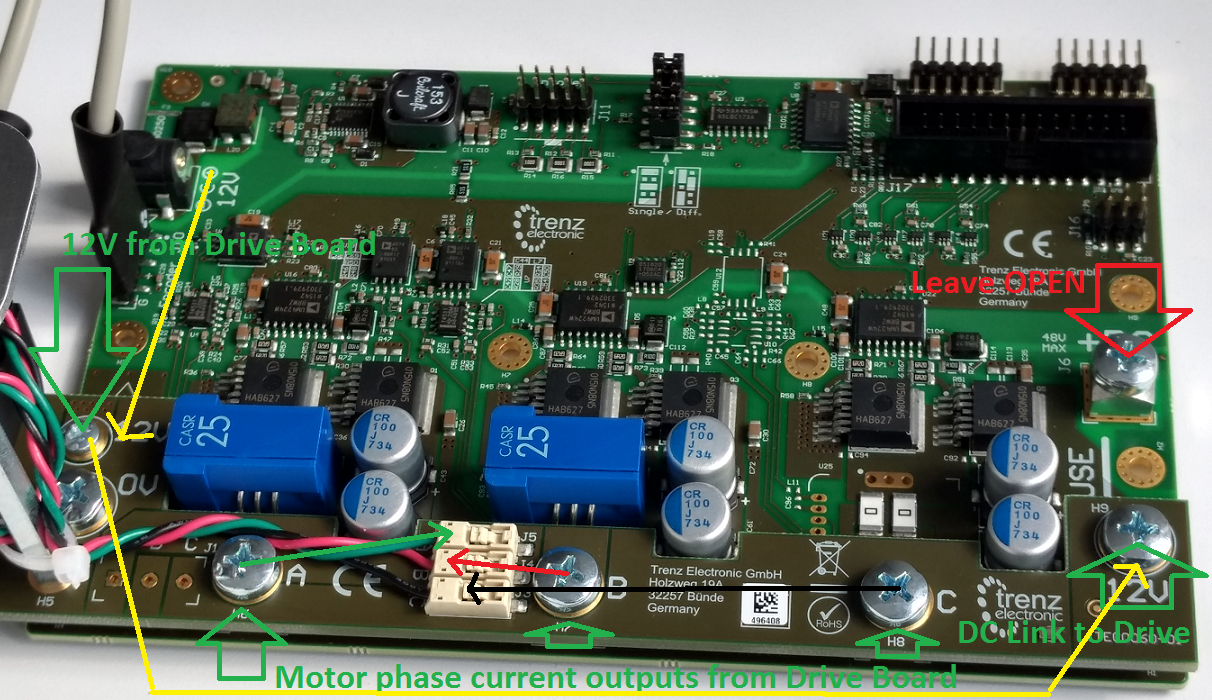
The Adapter board is mounted to Driver Board using 5 x M6 screws (Labels 0V, A, B, C, 12V on Adapter Board) and with M3 screws and spacer - marked 12V at the left. This Adapter board "forwards" (the yellow arrow) the Drive board pre-driver supply (12V) to the DC Link main terminal on the Drive board, so that separate DC Link powersupply is not needed allowing easy evaluation of the complete system.
Note terminal marked+DC must be left open when using the Adapter board!
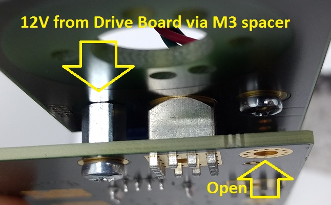
M3 Spacer and two M3 screws connect 12V from from Drive board to Adapter Board.
Motor Connection
When delivered as full EDDP Kit the reference Motor wires are already connected to Adapter board. Instructions for manual assembly below:
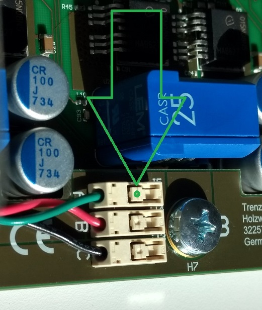
Green dot and arrow mark the place where wire terminal can be released for insertion or removal. Use a ball-point pen or similar tool to apply gentle force at the dot. Please do not try to remove the wires by pulling them out! Do not apply force in other regions of the white plastic than the one marked it is easy to damage the plastic.
Encoder Connection
One 6 Pin PMoD cable is included with the EDDP Kit, it is already assembled between encoder and Drive Board. Instructions for manual assembly below:
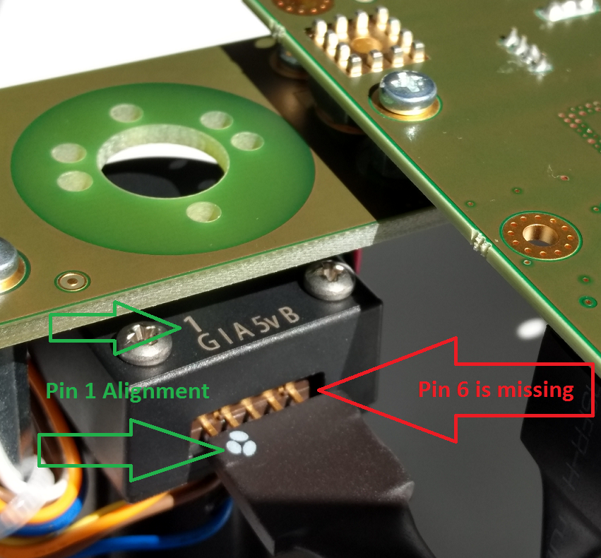
PMoD cable alignment to Encoder connector, notice that there are 5 pins in Encoder header while PMoD female connector has 6 terminals. Red Arrow marks the "empty" terminal at PMoD Cable.
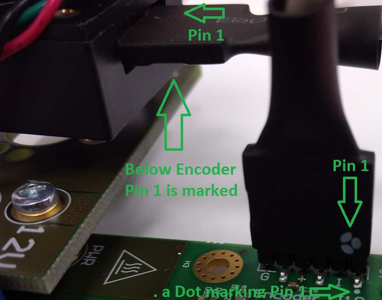
PMoD Cable installation, Pin 1 Markings highlighted, on Drive Board a white dot marks 6 Pin header Pin 1, also marked with "G" (ground). This pin should be aligned to Encoder Pin marked "G" and "1" visible when looking from the bottom up. Please note that Encoder header has 5 terminals while the driver board and PMoD cable have 6 terminals.
EDDP System Components
EDDP Kit Content
- Control Board: ARTY-Z-7010
- EDPS Driver Board: TEC0053
- EDPS Motor Adapter Board: TEC0060
- EDPS Reference Motor with Encoder: BLRW-111D-24V-10000-1000-SI
- Plastic DEMO load for Motor
- One 6 Pin PMoD cable
- Two 12V Power Supplies
- Screws and other accessories used to mount the motor
- One spare M6 Screw
- Plastic cover for Driver Board use without TEC0060
- 30A Fuse for Driver Board use without TEC0060
- Micro SD Card
- Quickstart Guide
The Motor is pre-mounted to the Driver board using the Adapter Board and accessories.
Control Board
The default Control Board is the Digilent ARTY-Z 7010, which is delivered as part of the EDDP Kit. This manual contains information relevent to the actual use of the ARTY-Z as a Control Board within the EDDP only; all technical data and user guides and manuals for the Controller Board are provided by the controller board manufacturer (Digilent Inc.). Use of the other Control boards with the EDPS Driver board is also outside the scope of this manual. Primary support for other control boards is currently provided by QDESYS.
Software
The software delivered on the SD card configures the FPGA on the ARTY-Z board with the Field-Oriented Control algorithm and starts the web server to serve the Web User Interface (Web UI).
To access the Web UI, point a web browser to the IP of the Controller Board. The following page appears:
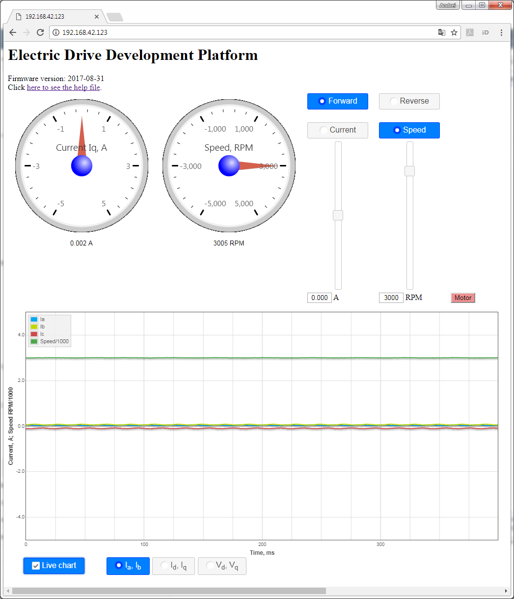
To start the motor, click the button "Motor". The motor will make 3 rotations in order to make sure that encoder finds the initial position before starting in correct mode and the button will turn red. To stop the motor, click the button "Motor" again; the button will turn green.
The gauges show the stator current Iq and the motor speed in RPM.
To see the charts live, enable checkbox "Live charts". The following charts are available:
- Ia,Ib - shows stator currents Ia,Ib, the calculated current Ic and motor speed.
- Id,Iq - shows stator currents Id, Iq and motor speed.
- Vd,Vq - shows stator voltages Vd and Vq.
The radio buttons "Current" and "Speed" permit switching the control modes.
The sliders permit selecting the target speed and target current when in the appropriate mode. The direction radio buttons "Forward" and "Reverse" will be changed accordingly when the sign of the value is changed.
The radio buttons "Forward" and "Reverse" can be used to change the direction; the target slider will be changed accordingly.
Motor/Encoder
The default motor is supplied in the EDDP Kit; see the chapter Reference Motor for details. Use of custom motors is outside the scope of this manual.
Block Diagram
Functional description
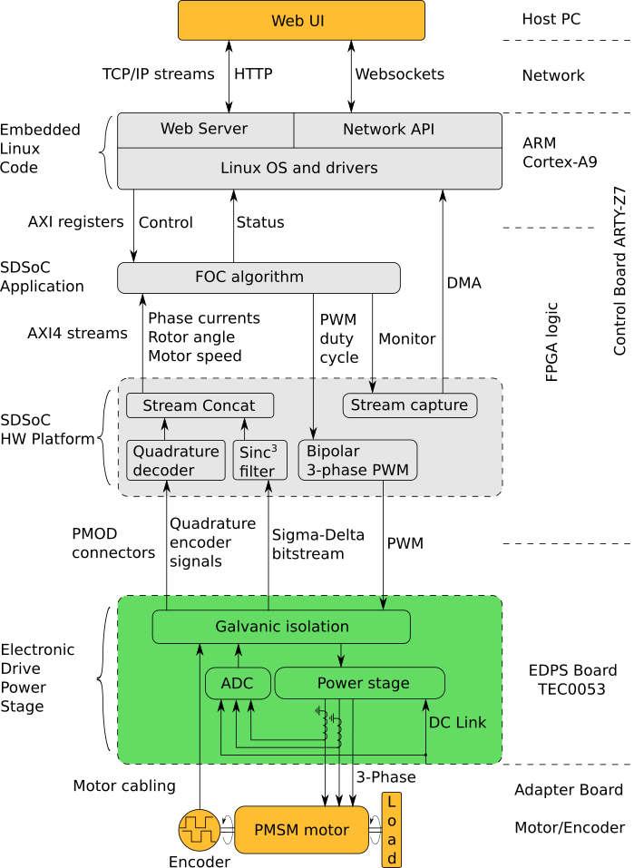
A 3-phase permanent-magnet synchronous motor with attached encoder and mechanical load is mounted to a EDPS Driver Board TEC0053 by using an Adapter Board TEC0060. The Driver Board is connected to a Control Board ARTY-Z7 through PMOD connectors. A Host PC running a Web Browser connects to the Control Board through a Network.
On the Driver Board, the 3-phase power stage drives the motor according to the PWM signal. The current transducers on the Driver Board transform the phase currents on 2 (optionally 3) phases into voltages, which, along with the DC Link voltage, are converted by ADC-s into a delta-sigma bitstream. The encoder signals and the sigma-delta bitstream are passed through the galvanic isolation to the Control Board. The PWM signal and ADC clock from the Control Board are passed through the galvanic isolation as well.
On the Control Board, the FPGA configuration is determined with the SDSoC Application built on top of the SDSoC Hardware Platform and the ARM Cortex-A9 CPU is running the Embedded Linux Code.
The SDSoC Hardware Platform provides a stream-oriented interface of the underlying hardware to the FOC algorithm. The streams are as follows:
- The data stream to the FOC algorithm consists of the concatenated stream of rotor angle and motor speeds and the stream of discrete ADC samples.
- The stream of PWM duty cycles from the FOC algorithm, which are converted to the PWM signals for the power stage.
- The stream of monitor data from the FOC algorithm, which is captured and written to the DMA buffer in the main memory. This monitor data stream can consist either of phase current data, stator current data or stator voltage data.
The SDSoC Application provides the FOC algorithm. The FOC algorithm operates on the AXI4 Stream to and from the SDSoC Hardware Platform and provides a set of AXI registers to control and monitor the status of the FOC algorithm. The control registers determine the FOC algorithm operating parameters and the source of the monitor data stream.
The Embedded Linux Code, running on the ARM Cortex-A9 CPU consists of the following:
- The Linux OS manages the hardware and provides execution environment for the programs to run in, which includes a TCP/IP network stack. The drivers included provide access to the control and status registers of the FOC algorithm and to the DMA buffer of the monitor data stream.
- The Network API is a server program, which provides an API built on top of Websockets protocol to control and monitor the FOC algorithm and to capture the monitor data stream.
- The Web Server, which is used to host the Web UI.
The Web UI running in a web browser on the Host PC enables one to operate the EDDP Kit from anywhere in a network.
List of the documents for further information:
| Title | Description |
|---|---|
| FOC SDSoC | Implementation of a Field-Oriented Control algorithm in C++ with Vivado SDSoC |
| SDSoC Hardware Platform ARTY-Z7 | A basis for building Vivado SDSoC applications running on an Arty-Z7 board connected to a TEC0053 board |
| AXI4-Stream AD7403 | An IP core for filtering the delta-sigma bitstream read from one or more ADC-s of type of AD7403 to an AXI4-Stream of samples |
| AXI4-Stream Encoder | An IP core for converting impulses from a relative index encoder with an index signal to an AXI4-Stream of position and speed data |
| AXI4-Stream PWM | An IP core for generating PWM signals according to the input AXI4-Stream |
| AXI4-Stream Concat | An IP core for concatenating AXI4-Streams |
| Web GUI | A Web UI to control and monitor an EDPS board over the Network API |
| Network API | A communication protocol, based on Websockets, to control an EDPS board |
| Embedded Linux Code | A server program interfacing to an EDPS board and implementing the Network API and the functions of a Web Server |
References
All resource links for other relevan documents and websites are available from Trenz EDDP Web Hub:
Disclaimer
Document Warranty
The material contained in this document is provided “as is” and is subject to being changed at any time without notice. Trenz Electronic does not warrant the accuracy and completeness of the materials in this document. Further, to the maximum extent permitted by applicable law, Trenz Electronic disclaims all warranties, either express or implied, with regard to this document and any information contained herein, including but not limited to the implied warranties of merchantability, fitness for a particular purpose or non infringement of intellectual property. Trenz Electronic shall not be liable for errors or for incidental or consequential damages in connection with the furnishing, use, or performance of this document or of any information contained herein.
Limitation of Liability
In no event will Trenz Electronic, its suppliers, or other third parties mentioned in this document be liable for any damages whatsoever (including, without limitation, those resulting from lost profits, lost data or business interruption) arising out of the use, inability to use, or the results of use of this document, any documents linked to this document, or the materials or information contained at any or all such documents. If your use of the materials or information from this document results in the need for servicing, repair or correction of equipment or data, you assume all costs thereof.
Copyright Notice
No part of this manual may be reproduced in any form or by any means (including electronic storage and retrieval or translation into a foreign language) without prior agreement and written consent from Trenz Electronic.
Technology Licenses
The hardware / firmware / software described in this document are furnished under a license and may be used /modified / copied only in accordance with the terms of such license.
Environmental Protection
To confront directly with the responsibility toward the environment, the global community and eventually also oneself. Such a resolution should be integral part not only of everybody's life. Also enterprises shall be conscious of their social responsibility and contribute to the preservation of our common living space. That is why Trenz Electronic invests in the protection of our Environment.
REACH, RoHS and WEEE
REACH
Trenz Electronic is a manufacturer and a distributor of electronic products. It is therefore a so called downstream user in the sense of REACH. The products we supply to you are solely non-chemical products (goods). Moreover and under normal and reasonably foreseeable circumstances of application, the goods supplied to you shall not release any substance. For that, Trenz Electronic is obliged to neither register nor to provide safety data sheet. According to present knowledge and to best of our knowledge, no SVHC (Substances of Very High Concern) on the Candidate List are contained in our products. Furthermore, we will immediately and unsolicited inform our customers in compliance with REACH - Article 33 if any substance present in our goods (above a concentration of 0,1 % weight by weight) will be classified as SVHC by the European Chemicals Agency (ECHA).
RoHS
Trenz Electronic GmbH herewith declares that all its products are developed, manufactured and distributed RoHS compliant.
WEEE
Information for users within the European Union in accordance with Directive 2002/96/EC of the European Parliament and of the Council of 27 January 2003 on waste electrical and electronic equipment (WEEE).
Users of electrical and electronic equipment in private households are required not to dispose of waste electrical and electronic equipment as unsorted municipal waste and to collect such waste electrical and electronic equipment separately. By the 13 August 2005, Member States shall have ensured that systems are set up allowing final holders and distributors to return waste electrical and electronic equipment at least free of charge. Member States shall ensure the availability and accessibility of the necessary collection facilities. Separate collection is the precondition to ensure specific treatment and recycling of waste electrical and electronic equipment and is necessary to achieve the chosen level of protection of human health and the environment in the European Union. Consumers have to actively contribute to the success of such collection and the return of waste electrical and electronic equipment. Presence of hazardous substances in electrical and electronic equipment results in potential effects on the environment and human health. The symbol consisting of the crossed-out wheeled bin indicates separate collection for waste electrical and electronic equipment.
Trenz Electronic is registered under WEEE-Reg.-Nr. DE97922676.
Overview
Content Tools