This step guides through the tasks which have to be done inside the Intel SoC Embedded Development Suite. As mentioned in page "Board bring-up overview for TEI0022" this step is for preloader and bootloader generation which should be done in the following next three steps:
- Preparation
- Preloader/Bootloader Generation
- Device Tree Generation
The section "Preparation" describes preparing steps which are necessary for the generation of the preloader and the bootloader which is described in section "Preloader/Bootloader Generation". After that in section "Device Tree Generation" the steps to create the device tree blob is explained.
/////
Requirements - EIGENTLICH ÜBERFLÜSSIG, da auf Seite 0 geschrieben... . ?!?
All steps to format / setup a bootable SD card can only be performed within a Linux,
(Windows Subsystem for Linux is not capable to format a SD card) the Linux tool fdisk / sfdisk depend on it.
The tools bsp-editor, alt-boot-disc-util and SoC EDS Command Shell are present.
An installation of INTEL SoC FPGA EMBEDDED DEVELOPMENT SUITE along with Intel Quartus Prime Lite, so the tools
bsp-editor, alt-boot-disc-util and SoC EDS Command Shell are present.
Background
The boot process of the HPS consists of several stages:
- Boot ROM
- Hard coded into the chip
- It's purpose is to detect the selected boot source
- Perform minimal Setup of the HPS
- Load the next Boot stage [Preloader / u-boot-spl] into the On chip RAM [OCRAM]
therefore the preloader / SPL u-boot is limited to 64 kByte on Cyclone 5 devices - Preloader
- Perform additional HPS initialization
- Bring up SDRAM
- Load the next boot stage from Flash to SDRAM and jump to it
- Preloader-optins:
u-boot - SPL
SoC EDS - MPL [Altera bare-metal libraries - HWLibs]
- For Cyclone 5 devices, the preloader consists of 4 identical copies. each 64 kB in size,
256 kb in total
- When generating the preloader, it can be necessary to manually add a header and checksum
into the binary, the tool mkpimage can perform these additions - Main Bootloader
- Load Linux [u-boot] or Bare Metal Application into the RAM
- Jump to it.
In case of Linux, load Kernel, followed by the loading of the Linux rootfs
- When generating the preloader, it can be necessary to manually add a header and checksum
into the binary, the tool mkimage can perform these additions
DIE GRAFIK GEHÖRT INTEL; DARF DIE HIER ÜBERHAUPT SEIN?---------------------------------------------------------

/////
Figure Boot Overview
Preparation
After compilation of the Intel Quartus project, described on page Intel Quartus Project, the folder "hps_isw_handoff" is existing inside the project folder. Therefore, if this folder does not exist fix the issue and return to this point.
BSP Editor
The BSP-Editor takes the handoff folder and generates further source and configuration files to be able to compile
the U-Boot Preloader and U-Boot Bootloader for the HPS.
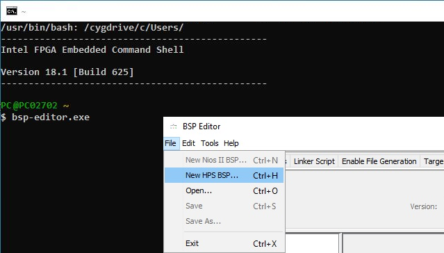
Like before mentioned, the SoC EDS Shell has limit access to the file system, so its the easiest solution to open a SoC EDS Shell
with administrative privileges. Use your file browser and navigate to C:\intelFPGA\18.1\embedded\ .
Right click onto the Embedded_Command_Shell.bat , select Run as administrator and click onto Yes in the
window - User Account Control .
Type into the Shell bsp-editor.exe and press Enter. The BSP-Editor window opens.
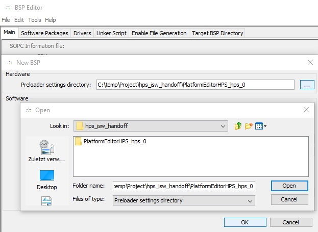
Via File → New HPS BSP... open the dialogue - New BSP - , click onto the tree doted button and point in the next
window - Open - to the folder PlatformEditorHPS_hps_0 inside your handoff folder, locate inside your project folder.
Press open, the window closes and then press OK, the dialogue closes.
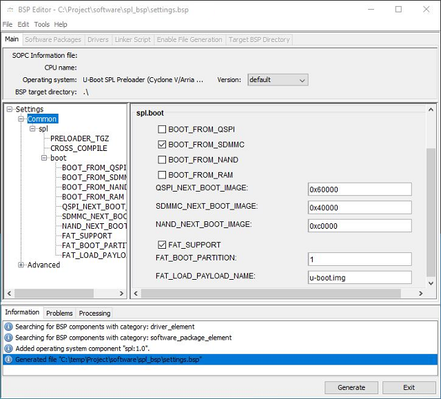
Back in the BSP-Editor, the U-Boot preloader must be configured. In the right column, under spl.boot are four Checkboxes,
each beginning with BOOT_FROM_... check only BOOT_FROM_SDMMC , the following three lines are of no interest.
check FAT_SUPPORT , FAT_BOOT_PARTITION: must contain a 1 and FAT_LOAD_PAYLOAD_NAME: must contain u-boot.img .
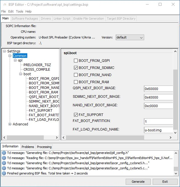
Hit the button Generate in the bottom right corner, after processing, in the bottom tab Information
Finished generation BSP files. Total time taken = x seconds is visible.
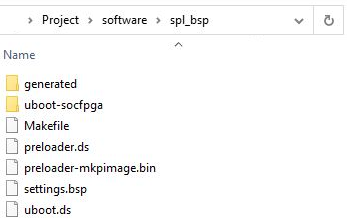
In your project folder, the folder - software - appears.
U-Boot - Make preloader and main bootloader
The handoff folder contains now after the previous steps all the sources to compile the booot loaders.
On Windows 10 - Version 1909 - and cygwin - Version 2.0 - all commands which require decompressing of source archives, have to be
pointed into the right folder to be executed from, these commands beginn with /usr/bin/ . All commands are in italic and bold,
comments to commands are in brackets.
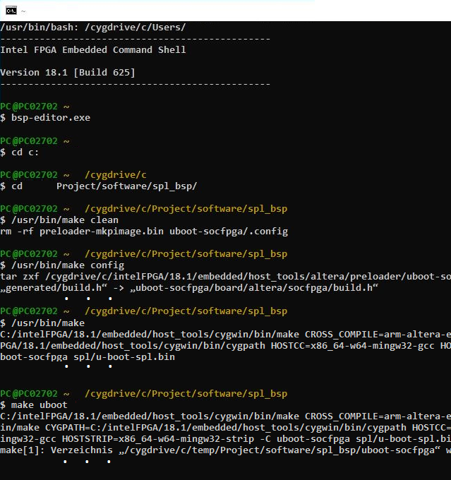
First, the software folder needs to be setup, therefore navigate to it by typing into the prior opened SoC EDS Shell with
administrative privileges
cd c: (Change directory)
followed by
cd Project/software/spl_bsp
and run two setup commands.
/usr/bin/make clean (Cleans the folder from files of a previous build)
/usr/bin/make config (generates folder: uboot-socfpga into softwae/spl_bsp)
The following command decompresses and places the general U-Boot source folder inside the folder. In addition it generates
the preloader image - preloader-mkpimage.bin - and some more files.
/usr/bin/make (Places the file: preloader-mkpimage.bin into softwae/spl_bsp)
To generate the main U-Boot boot loader, type:
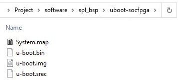
make uboot (Places the image u-boot.img into softwae/spl_bsp/uboot-socfpga)
Device Tree Blob
Lastly, the Device Tree Blob must be generated, whereby Linux can start automated without user interaction.
It acts as an Interface from the board hardware to the Linux Kernel. The .dtb file informs the Linux Kernel about the existing Hardware,
its Configuration and which driver to use for controlling it.
Generate - .dtb or .dts file from .sopcinfo file
c:\intelFPGA\18.1\embedded\examples\hardware\cv_soc_devkit_ghrd\tgz\soc_system_18_1_09132018_94307.tar.gz
To generate the .dtb file, a folder containing the Golden Hardware Reference Design for Cyclone 5 FPGA's is required. A copy of it is
part of Intels SoC FPGA Embedded Development Suite. To be on the safe side, copy the file
soc_system_18_1_09132018_94307.tar.gz
inside the folder
c:\intelFPGA\18.1\embedded\examples\hardware\cv_soc_devkit_ghrd\tgz\
to new folder inside your project directory, for example,
c:\Project\ghrd_cyc5
via a file browser.
Use a SoC EDS SHell with administrative privileges to navigate to your newly folder
cd c:/Project/ghrd_cyc5
and extract the .tar.gz archieve .
tar xvf soc_system_18_1_09132018_94307.tar.gz (Decompress the archieve)
Copy the file HPSexample.sopcinfo from the project folder into this subfolder (c:/Project/ghrd_cyc5).
Enter into the Shell the following command:
sopc2dts --input HPS.sopcinfo --output DTBsocfpga.dtb --type dtb --board hps_common_board_info.xml --bridge-removal all --clocks
Kurzform:
sopc2dts -i HPS.sopcinfo -o DTBsocfpga.dtb -t dtb --board hps_common_board_info.xml --bridge-removal all --clocks
In case a .dts file is desired, use this command:
sopc2dts -i HPS.sopcinfo -o DTBsocfpga.dts -t dts --board hps_common_board_info.xml --bridge-removal all --clocks
--------------
$ sopc2dts.exe --input PlatformEditorHPS.sopcinfo --output DTBsocfpga.dts --type dts --board hps_common_board_info.xml
--bridge-removal all --clocks
MasterIF sopc2dts.lib.components.Interface@76fb509a slaveIF null
MasterIF sopc2dts.lib.components.Interface@76fb509a slaveIF null
DTAppend: Unable to find parent, null, for #address-cells. Adding to root
DTAppend: Unable to find parent, null, for #size-cells. Adding to root
DTAppend: Unable to find parent, null, for reg. Adding to root
DTAppend: Unable to find parent, null, for spi-max-frequency. Adding to root
DTAppend: Unable to find parent, null, for m25p,fast-read. Adding to root
DTAppend: Unable to find parent, null, for page-size. Adding to root
DTAppend: Unable to find parent, null, for block-size. Adding to root
DTAppend: Unable to find parent, null, for tshsl-ns. Adding to root
DTAppend: Unable to find parent, null, for tsd2d-ns. Adding to root
DTAppend: Unable to find parent, null, for tchsh-ns. Adding to root
DTAppend: Unable to find parent, null, for tslch-ns. Adding to root
DTAppend: Unable to find parent, null, for cdns,page-size. Adding to root
DTAppend: Unable to find parent, null, for cdns,block-size. Adding to root
DTAppend: Unable to find parent, null, for cdns,read-delay. Adding to root
DTAppend: Unable to find parent, null, for cdns,tshsl-ns. Adding to root
DTAppend: Unable to find parent, null, for cdns,tsd2d-ns. Adding to root
DTAppend: Unable to find parent, null, for cdns,tchsh-ns. Adding to root
DTAppend: Unable to find parent, null, for cdns,tslch-ns. Adding to root
--------------
Decompile - .dtb file to .dts file
C:\intelFPGA\18.1\embedded\host_tools\gnu\dtc\ dtc.exe
cd /cygdrive/c/intelFPGA/18.1/embedded/host_tools/gnu/dtc
dtc -I dts -O dtb -o device-tree.dtb devicetree.dts
Generate - .dts file to .dtb file
cd /cygdrive/c/intelFPGA/18.1/embedded/host_tools/gnu/dtc
dtc -I dtb -O dts -o devicetree.dts soc_system.dtb
Overview
Content Tools