Overview
Refer to http://trenz.org/te0955-info for the current online version of this manual and other available documentation.
Key Features
- Vitis/Vivado 2025.2
- PetaLinux 2025.2
- SD
- eMMC
- ETH
- USB
- I2C
- MAC from EEPROM
- User LEDs
- PCIe
- NVMe SSD
- PWM / Fan Controller
Revision History
Release Notes and Know Issues
| Issues | Description | Workaround | To be fixed version |
|---|
Known Issues
Requirements
Software
| Software | Version | Note |
|---|---|---|
| Vivado | 2025.2 | needed |
| Vitis | 2025.2 | needed, Vitis is included in Vivado installation |
| PetaLinux | 2025.2 | needed |
| Vitis HLS | 2025.2 | needed (used for MIPI-Camera Pipeline) Vitis HLS is included optionally in Vivado installation |
Software
Hardware
Basic description of TE Board Part Files is available on TE Board Part Files.
Complete List is available on "<project folder>\board_files\*_board_files.csv"
Design supports following modules:
Design supports following carriers:
| Carrier model | Notes |
|---|---|
| TEB0955* |
*used as reference
Additional HW Requirements:
| Additional Hardware | Notes |
|---|---|
| Micro USB Cable for JTAG/UART | Check Carrier Board and Programmer for correct type |
| Cooler | It is strongly recommended that the module should be used with heat sink. The reference design can drive a fan depending on the temprature of the Versal chip. |
| Ethernet cable | |
| SD card | 16GB |
| PC | |
| SSD Memory (optional) | SSD storage on the M.2 U5 connector on the back of the board |
Additional Hardware
Content
For general structure and of the reference design, see Project Delivery - AMD devices
Design Sources
| Type | Location | Notes |
|---|---|---|
| Vivado | <project folder>\block_design <project folder>\constraints <project folder>\ip_lib <project folder>\board_files | Vivado Project will be generated by TE Scripts |
| Vitis | <project folder>\sw_lib | Additional Software Template for Vitis and apps_list.csv with settings automatically for Vitis app generation |
| PetaLinux | <project folder>\os\petalinux | PetaLinux template with current configuration |
Design sources
Additional Sources
| Type | Location | Notes |
|---|---|---|
| init.sh | <project folder>\misc\sd\ | Additional Initialisation Script for Linux |
Additional design sources
Prebuilt
File | File-Extension | Description |
|---|---|---|
| BIF-File | *.bif | File with description to generate Bin-File |
| BIN-File | *.bin | Flash Configuration File with Boot-Image (Versal-FPGAs) |
| BIT-File | *.pdi | FPGA Configuration File |
| Boot Script-File | *.scr | Distro Boot Script file |
| Debug Probes-File | *.ltx | Definition File for Vivado/Vivado Labtools Debugging Interface |
| Diverse Reports | --- | Report files in different formats |
| Hardware-Platform-Description-File | *.xsa | Exported Vivado hardware description file for Vitis and PetaLinux |
| LabTools Project-File | *.lpr | Vivado Labtools Project File |
| OS-Image | *.ub | Image with Linux Kernel (On Petalinux optional with Devicetree and RAM-Disk) |
| Software-Application-File | *.elf | Software Application for Zynq or MicroBlaze Processor Systems |
Prebuilt files (only on ZIP with prebuilt content)
Download
Reference Design is only usable with the specified Vivado/Vitis/PetaLinux version. Do never use different Versions of Xilinx Software for the same Project.
Reference Design is available on:
Design Flow
Reference Design is available with and without prebuilt files. It's recommended to use TE prebuilt files for first launch.
Trenz Electronic provides a tcl based built environment based on Xilinx Design Flow.
See also:
- AMD Development Tools#XilinxSoftware-BasicUserGuides
- Vivado Projects - TE Reference Design
- Project Delivery
The Trenz Electronic FPGA Reference Designs are TCL-script based project. Command files for execution will be generated with "_create_win_setup.cmd" on Windows OS and "_create_linux_setup.sh" on Linux OS.
TE Scripts are only needed to generate the vivado project, all other additional steps are optional and can also executed by Xilinx Vivado/Vitis GUI. For currently Scripts limitations on Win and Linux OS see: Project Delivery Currently limitations of functionality
Caution! Win OS has a 260 character limit for path lengths which can affect the Vivado tools. To avoid this issue, use Virtual Drive or the shortest possible names and directory locations for the reference design (for example "x:\<project folder>")
Run _create_win_setup.cmd/_create_linux_setup.sh and follow instructions on shell:
_create_win_setup.cmd/_create_linux_setup.sh------------------------Set design paths---------------------------- -- Run Design with: _create_win_setup -- Use Design Path: <absolute project path> -------------------------------------------------------------------- -------------------------TE Reference Design--------------------------- -------------------------------------------------------------------- -- (0) Module selection guide, project creation...prebuilt export... -- (1) Create minimum setup of CMD-Files and exit Batch -- (2) Create maximum setup of CMD-Files and exit Batch -- (3) (internal only) Dev -- (4) (internal only) Prod -- (c) Go to CMD-File Generation (Manual setup) -- (d) Go to Documentation (Web Documentation) -- (g) Install Board Files from Xilinx Board Store (beta) -- (a) Start design with unsupported Vivado Version (beta) -- (x) Exit Batch (nothing is done!) ---- Select (ex.:'0' for module selection guide):
- Press 0 and enter to start "Module Selection Guide"
- Create project and follow instructions of the product selection guide, settings file will be configured automatically during this process.
optional for manual changes: Select correct device and Xilinx install path on "design_basic_settings.cmd" and create Vivado project with "vivado_create_project_guimode.cmd"
Note: Select correct one, see also Vivado Board Part Flow
Create hardware description file (.xsa file) for PetaLinux project and export to prebuilt folder
run on Vivado TCL (Script generates design and export files into "<project folder>\prebuilt\hardware\<short name>")TE::hw_build_design -export_prebuilt
Using Vivado GUI is the same, except file export to prebuilt folder.
- Create and configure your petalinux project with exported .xsa-file, see PetaLinux KICKstart
- use TE Template from "<project folder>\os\petalinux"
use exported .xsa file from "<project folder>\prebuilt\hardware\<short name>" . Note: HW Export from Vivado GUI creates another path as default workspace.
- (Optional) Configure the boot.scr file as needed, see Distro Boot
- Generate Programming Files with Vitis (recommended)
- Copy petaLinux build image files to prebuilt folder
- copy u-boot.elf, system.dtb, bl31.elf, image.ub and boot.scr from "<plnx-proj-root>/images/linux" to prebuilt folder
"<project folder>\prebuilt\os\petalinux\<ddr size>" or "<project folder>\prebuilt\os\petalinux\<short name>"
- copy u-boot.elf, system.dtb, bl31.elf, image.ub and boot.scr from "<plnx-proj-root>/images/linux" to prebuilt folder
- Generate Programming Filesrun on Vivado TCL (Script generates applications and bootable files, which are defined in "test_board\sw_lib\apps_list.csv")
TE::sw_run_vitis -all
TE::sw_run_vitis (optional; Start Vitis from Vivado GUI or start with TE Scripts on Vivado TCL)
TCL scripts generate also platform project, this must be done manually in case GUI is used. See Vitis
- Copy petaLinux build image files to prebuilt folder
- Generate Programming Files with Petalinux (alternative), see PetaLinux KICKstart
Launch
Programming
Check Module and Carrier TRMs for proper HW configuration before you try any design.
Reference Design is also available with prebuilt files. It's recommended to use TE prebuilt files for first launch.
Xilinx documentation for programming and debugging: Vivado/Vitis/SDSoC-Xilinx Software Programming and Debugging
Note: Depending on Boot Mode settings, QSPI boot with Linux image on SD or complete SD Boot is possible.
Get prebuilt boot binaries
- Run _create_win_setup.cmd/_create_linux_setup.sh and follow instructions on shell
- Press 0 and enter to start "Module Selection Guide"
- Select assembly version
- Validate selection
Select create and open delivery binary folder
Note: Folder "<project folder>/_binaries_<Article Name>" with subfolder "boot_<app name>" for different applications will be generated
OSPI-Boot mode
Option for BOOT.bin on OSPI Flash and image.ub and boot.scr on SD or USB.
- Connect JTAG and power on carrier with module
Open Vivado Project with "vivado_open_existing_project_guimode.cmd" or if not created, create with "vivado_create_project_guimode.cmd"
run on Vivado TCL (Script programs BOOT.bin on QSPI flash)TE::pr_program_flash -swapp u-boot TE::pr_program_flash -swapp hello_te0955 (optional)
- Copy image.ub and boot.scr on SD or USB
- use files from "<project folder>\_binaries_<Article Name>\boot_linux" from generated binary folder,see: Get prebuilt boot binaries
- or use prebuilt file location, see "<project folder>\prebuilt\file_location.txt"
- Set Boot Mode to OSPI-Boot and insert SD or USB.
- Depends on Carrier, see carrier TRM.
SD-Boot mode
- Copy image.ub, boot.src and BOOT.bin on SD card
- use files from "<project folder>\_binaries_<Article Name>\boot_linux" from generated binary folder, see: Get prebuilt boot binaries
- or use prebuilt file location, see "<project folder>\prebuilt\file_location.txt"
- Set Boot Mode to SD-Boot.
- Depends on Carrier, see carrier TRM.
- Insert SD-Card in SD-Slot.
JTAG
Not used on this example.
Usage
- Prepare HW like described on section Programming
- Connect UART USB (most cases same as JTAG)
Select SD Card as Boot Mode (or QSPI - depending on step 1)
Note: See TRM of the Carrier, which is used.
Starting with Petalinux version 2020.1, the industry standard "Distro-Boot" boot flow for U-Boot was introduced, which significantly expands the possibilities of the boot process and has the primary goal of making booting much more standardised and predictable.
The boot options described above describe the common boot processes for this hardware; other boot options are possible.
For more information see Distro BootPower On PCB
Linux
- Open Serial Console (e.g. putty)
- Speed: 115200
select COM Port
Win OS, see device manager, Linux OS see dmesg |grep tty (UART is *USB1)
Linux Console:
Note: Wait until Linux boot finished
You can use Linux shell now.
i2cdetect -y -r 0	(check I2C 0 Bus)
dmesg | grep rtc	(RTC check)
udhcpc				(ETH0 check)
lsusb				(USB check)
lspci               (PCIe check)
lsmem               (DDR memory check)
Option Features
- init.sh scripts
- add init.sh script on SD, content will be load automatically on startup (template included in "<project folder>\misc\SD")
- init.sh scripts
Vivado HW Manager
System Design - Vivado
Block Design
PCB REV03
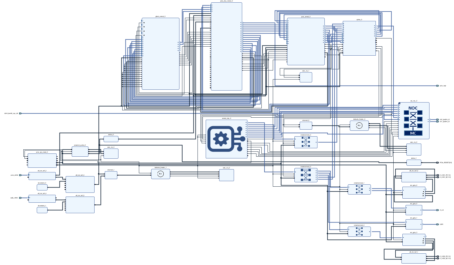
Block Design PCB REV03
PS Interfaces
Activated interfaces:
| Type | Note |
|---|---|
| DDR | |
| QSPI | MIO |
| SD0 | MIO |
| SD1 | MIO |
| I2C0 | MIO |
| UART0 | MIO |
| GPIO0 | MIO |
| SWDT0..1 | |
| TTC0..3 | |
| GEM3 | MIO |
| USB0 | MIO |
PS Interfaces
| Type | Note |
|---|---|
| DDR | |
| OSPI | MIO |
| SD0/eMMC | MIO |
| SD1/(SD2.0 and SD3.0) | MIO |
| PMC_I2C | MIO |
| UART0 | MIO |
| GEM0 | MIO |
| USB0 | MIO, USB2.0 |
| TTC0 | MIO (PWM) |
Constrains
Design specific constraints
_i_io.xdc
 ####################################################################################
# IO Standard definition
####################################################################################
set_property IOSTANDARD DIFF_HSTL_I_12 [get_ports {C_HS1_P[*]}]
set_property IOSTANDARD DIFF_HSTL_I_12 [get_ports {C_HS2_P[*]}]
set_property IOSTANDARD LVCMOS33 [get_ports {C_LS_tri_io[7]}]
set_property IOSTANDARD LVCMOS33 [get_ports {C_LS_tri_io[6]}]
set_property IOSTANDARD LVCMOS33 [get_ports {C_LS_tri_io[5]}]
set_property IOSTANDARD LVCMOS33 [get_ports {C_LS_tri_io[4]}]
set_property IOSTANDARD LVCMOS33 [get_ports {C_LS_tri_io[3]}]
set_property IOSTANDARD LVCMOS33 [get_ports {C_LS_tri_io[2]}]
set_property IOSTANDARD LVCMOS33 [get_ports {C_LS_tri_io[1]}]
set_property IOSTANDARD LVCMOS33 [get_ports {C_LS_tri_io[0]}]
set_property IOSTANDARD DIFF_HSTL_I_12 [get_ports {C_HS1_P[*]}]
set_property IOSTANDARD DIFF_HSTL_I_12 [get_ports {C_HS2_P[*]}]
set_property IOSTANDARD LVCMOS33 [get_ports {USR_tri_io[0]}]
set_property IOSTANDARD LVSTL_11 [get_ports {PCIe_RESET[0]}]
set_property IOSTANDARD DIFF_HSTL_I_12 [get_ports {C_HS1_P[*]}]
set_property IOSTANDARD DIFF_HSTL_I_12 [get_ports {C_HS2_P[*]}]

####################################################################################
# Clock definition
####################################################################################
create_clock -period 10.000 [get_ports pcie_refclk_clk_p]

create_clock -period 10 [get_ports pcie_refclk_clk_p];                                      # pcie_refclk frequency 100MHz
create_clock -period 4 [get_pins -hierarchical -regexp vsys_i/gt_quad_base_0/ch0_rxoutclk]; # ch0_rxoutclk frequency 250MHz
create_clock -period 2 [get_pins -hierarchical -regexp vsys_i/gt_quad_base_0/ch0_txoutclk]; # ch0_txoutclk frequency 500MHz


####################################################################################
# Pins allocation
####################################################################################
# CRUVI low speed
set_property PACKAGE_PIN A13 [get_ports {C_LS_tri_io[0]}];  #C_LS_C_D0
set_property PACKAGE_PIN B13 [get_ports {C_LS_tri_io[1]}];  #C_LS_C_D1
set_property PACKAGE_PIN A14 [get_ports {C_LS_tri_io[2]}];  #C_LS_C_D2
set_property PACKAGE_PIN B12 [get_ports {C_LS_tri_io[3]}];  #C_LS_C_D3
set_property PACKAGE_PIN B11 [get_ports {C_LS_tri_io[4]}];  #C_LS_C_SDA
set_property PACKAGE_PIN A10 [get_ports {C_LS_tri_io[5]}];  #C_LS_C_SCL
set_property PACKAGE_PIN A11 [get_ports {C_LS_tri_io[6]}];  #C_LS_C_SCK
set_property PACKAGE_PIN B10 [get_ports {C_LS_tri_io[7]}];  #C_LS_C_SEL


# CRUVI high speed 1
set_property IOSTANDARD DIFF_HSTL_I_12 [get_ports {C_HS1_P[*]}]

set_property PACKAGE_PIN J27 [get_ports {C_HS1_P[0]}];      # C_HC_X_B0 (J1-15)
set_property PACKAGE_PIN B26 [get_ports {C_HS1_P[1]}];      # C_HS_X_B1 (J1-21)
set_property PACKAGE_PIN E27 [get_ports {C_HS1_P[2]}];      # C_HS_X_B2 (J1-27)
set_property PACKAGE_PIN H27 [get_ports {C_HS1_P[3]}];      # C_HS_X_B3 (J1-33)
set_property PACKAGE_PIN G27 [get_ports {C_HS1_P[4]}];      # C_HS_X_B4 (J1-39)
set_property PACKAGE_PIN C27 [get_ports {C_HS1_P[5]}];      # C_HS_X_B5 (J1-45)
set_property PACKAGE_PIN H25 [get_ports {C_HS1_P[6]}];      # C_HS_X_A0 (J1-14)
set_property PACKAGE_PIN G25 [get_ports {C_HS1_P[7]}];      # C_HS_X_A1 (J1-20)
set_property PACKAGE_PIN F26 [get_ports {C_HS1_P[8]}];      # C_HS_X_A2 (J1-26)
set_property PACKAGE_PIN A25 [get_ports {C_HS1_P[9]}];      # C_HS_X_A3 (J1-32)
set_property PACKAGE_PIN D27 [get_ports {C_HS1_P[10]}];     # C_HS_X_A4 (J1-38)
set_property PACKAGE_PIN C25 [get_ports {C_HS1_P[11]}];     # C_HS_X_A5 (J1-44)

# CRUVI high speed 2
set_property IOSTANDARD DIFF_HSTL_I_12 [get_ports {C_HS2_P[*]}]

set_property PACKAGE_PIN G21 [get_ports {C_HS2_P[0]}];      # C_HC_Y_B0 (J2-15)
set_property PACKAGE_PIN A23 [get_ports {C_HS2_P[1]}];      # C_HS_Y_B1 (J2-21)
set_property PACKAGE_PIN B20 [get_ports {C_HS2_P[2]}];      # C_HS_Y_B2 (J2-27)
set_property PACKAGE_PIN E20 [get_ports {C_HS2_P[3]}];      # C_HS_Y_B3 (J2-33)
set_property PACKAGE_PIN D20 [get_ports {C_HS2_P[4]}];      # C_HS_Y_B4 (J2-39)
set_property PACKAGE_PIN C22 [get_ports {C_HS2_P[5]}];      # C_HS_Y_B5 (J2-45)
set_property PACKAGE_PIN H23 [get_ports {C_HS2_P[6]}];      # C_HS_Y_A0 (J2-14)
set_property PACKAGE_PIN F22 [get_ports {C_HS2_P[7]}];      # C_HS_Y_A1 (J2-20)
set_property PACKAGE_PIN E22 [get_ports {C_HS2_P[8]}];      # C_HS_Y_A2 (J2-26)
set_property PACKAGE_PIN C23 [get_ports {C_HS2_P[9]}];      # C_HS_Y_A3 (J2-32)
set_property PACKAGE_PIN A20 [get_ports {C_HS2_P[10]}];     # C_HS_Y_A4 (J2-38)
set_property PACKAGE_PIN D24 [get_ports {C_HS2_P[11]}];     # C_HS_Y_A5 (J2-44)

# USR GPIOs
set_property PACKAGE_PIN D14 [get_ports {USR_tri_io[0]}]

# PCIe Reset Signal
set_property PACKAGE_PIN M25 [get_ports {PCIe_RESET[0]}]


# M2 (PCIe) interface
set_property PACKAGE_PIN K7 [get_ports {qsfp_refclk_clk_p[0]}]
set_property PACKAGE_PIN K6 [get_ports {qsfp_refclk_clk_n[0]}]

set_property PACKAGE_PIN H7 [get_ports {pcie_refclk_clk_p[0]}]
set_property PACKAGE_PIN H6 [get_ports {pcie_refclk_clk_n[0]}]

set_property PACKAGE_PIN F2 [get_ports {pcie_mgt_grx_p[0]}]
set_property PACKAGE_PIN F1 [get_ports {pcie_mgt_grx_n[0]}]
set_property PACKAGE_PIN E5 [get_ports {pcie_mgt_gtx_p[0]}]
set_property PACKAGE_PIN E4 [get_ports {pcie_mgt_gtx_n[0]}]
set_property PACKAGE_PIN D2 [get_ports {pcie_mgt_grx_p[1]}]
set_property PACKAGE_PIN D1 [get_ports {pcie_mgt_grx_n[1]}]
set_property PACKAGE_PIN D8 [get_ports {pcie_mgt_gtx_p[1]}]
set_property PACKAGE_PIN D7 [get_ports {pcie_mgt_gtx_n[1]}]
set_property PACKAGE_PIN B2 [get_ports {pcie_mgt_grx_p[2]}]
set_property PACKAGE_PIN B1 [get_ports {pcie_mgt_grx_n[2]}]
set_property PACKAGE_PIN C5 [get_ports {pcie_mgt_gtx_p[2]}]
set_property PACKAGE_PIN C4 [get_ports {pcie_mgt_gtx_n[2]}]
set_property PACKAGE_PIN A5 [get_ports {pcie_mgt_grx_p[3]}]
set_property PACKAGE_PIN A4 [get_ports {pcie_mgt_grx_n[3]}]
set_property PACKAGE_PIN B8 [get_ports {pcie_mgt_gtx_p[3]}]
set_property PACKAGE_PIN B7 [get_ports {pcie_mgt_gtx_n[3]}]
Software Design - Vitis
For Vitis project creation, follow instructions from:
Application
Template location: "<project folder>\sw_lib\sw_apps\"versal_plm
Xilinx default PLM firmware.
versal_psm
Xilinx default PSM firmware.
hello_te0955
Hello TE0955 is a Xilinx Hello World example as endless loop instead of one console output.
u-boot
U-Boot.elf is generated with PetaLinux. Vitis is used to generate BOOT.bin.
Software Design - PetaLinux
For PetaLinux installation and project creation, follow instructions from:
Config
Start with petalinux-config or petalinux-config --get-hw-description
Changes:
- Identification
- CONFIG_SUBSYSTEM_HOSTNAME="Trenz"
- CONFIG_SUBSYSTEM_PRODUCT="TE0955"
U-Boot
Start with petalinux-config -c u-boot
Changes:
- Read MAC from EEPROM:
CONFIG_DM_RTC=y
CONFIG_NVMEM=y
- CONFIG_SPI_FLASH_SOFT_RESET=y
Device Tree
project-spec\meta-user\recipes-bsp\device-tree\files\system-user.dtsi
/include/ "system-conf.dtsi"

/include/ "pl-custom.dtsi"
/{
};

#include <dt-bindings/gpio/gpio.h>
#include <dt-bindings/interrupt-controller/irq.h>

/*------------------ eMMC --------------------*/
&sdhci0 {
	bus-width = <8>;
};

/*------------------ OSPI --------------------*/
&ospi {

	bus-num = <2>;
	num-cs = <1>;

	flash@0 {
		compatible = "mt35xu02g", "micron,m25p80", "jedec,spi-nor";
		reg = <0>;

		cdns,read-delay = <0x0>;
		cdns,tshsl-ns = <0x0>;
		cdns,tsd2d-ns = <0x0>;
		cdns,tchsh-ns = <0x1>;
		cdns,tslch-ns = <0x1>;

		spi-rx-bus-width = <8>;
		spi-tx-bus-width = <8>;
		spi-max-frequency = <20000000>; 	// Set frequency according to the AMD reference design
		reset-gpios = <&gpio1 12 GPIO_ACTIVE_LOW>;
		#address-cells = <1>;
		#size-cells = <1>;
	};
};

/*------------------ ETH PHY --------------------*/
&gem0 {
	phy-handle = <&phy0>;

	nvmem-cells = <ð0_addr>;
	nvmem-cell-names = "mac-address";

	//required otherwise petalinux gives a static address here
	/delete-property/ local-mac-address;

	mdio {
		phy0: phy0@3 {
			device_type = "ethernet-phy";
			reg = <3>;

			//only needed because of reset-gpios present
			//compatible = "ethernet-phy-id0022.1652"; //uboot: [mii read PHYAD 2].[mii read PHYAD 3]

			//reset-names = "ETH_RESET";
			//reset-gpios = <&gpio0 49 GPIO_ACTIVE_LOW>; //careful this is the #RST
			//reset-assert-us = <10000>; //minimum duration according to datasheet 10ms
			//reset-deassert-us = <2000>;
		};
	};
};

/*------------------ GPIO MISC --------------------*/
&gpio0 {
	status = "okay";
	gpio-line-names =
		"", "", "", "", "", "", "", "", "", "",
		"", "", "", "", "GPIO3_LS", "GPIO1_LS", "", "", "", "",
		"M_INT_PS#", "U_INT_PS#", "GPIO2_LS", "DC_OM_I2C";
};

&gpio1 {
	status = "okay";
	gpio-line-names =
		"", "", "", "", "", "", "", "", "", "",
		"", "", "OSPI_opt", "", "", "", "", "", "", "",
		"", "", "", "", "", "", "", "", "", "",
		"", "", "", "", "", "", "", "GPIO0", "", "PERST0#",
		"", "", "", "", "", "", "", "", "RST#", "",
		"", "", "", "", "", "", "", "", "", "";
};

/*------------------ USB --------------------*/
&dwc3_0 {
	dr_mode = "host";
};

/*------------------ I2C --------------------*/

&i2c2 {
	status = "okay";

	eeprom: eeprom@53 {
		compatible = "microchip,24aa025", "atmel,24c02";
		reg = <0x53>;

		#address-cells = <1>;
		#size-cells = <1>;
		eth0_addr: eth-mac-addr@FA {
			reg = <0xFA 0x06>;
		};
	};

	pcf8574: gpio@25 {
		compatible = "nxp,pcf8574";
		reg = <0x25>;
		gpio-controller;
		#gpio-cells = <2>;
	};

	sysmon@45 {
		compatible = "xlnx,versal-sysmon";
		reg = <0x45>;
		xlnx,numchannels = /bits/8 <27>;
		#address-cells = <1>;
		#size-cells = <0>;

		supply@7 {
			reg = <0x07>;
			xlnx,name = "vccaux";
		};

		supply@9 {
			reg = <0x09>;
			xlnx,name = "vccaux_smon";
		};

		supply@6 {
			reg = <0x06>;
			xlnx,name = "vccint";
		};

		supply@4 {
			reg = <0x04>;
			xlnx,name = "vcc_ram";
		};

		supply@5 {
			reg = <0x05>;
			xlnx,name = "vcc_soc";
		};

		supply@25 {
			reg = <0x19>;
			xlnx,name = "gtyp_avccaux_104";
		};

		supply@23 {
			reg = <0x17>;
			xlnx,name = "gtyp_avcc_104";
		};

		supply@21 {
			reg = <0x15>;
			xlnx,name = "gtyp_avtt_104";
		};

		supply@24 {
			reg = <0x18>;
			xlnx,name = "gtyp_avccaux_103";
		};

		supply@22 {
			reg = <0x16>;
			xlnx,name = "gtyp_avcc_103";
		};

		supply@20 {
			reg = <0x14>;
			xlnx,name = "gtyp_avtt_103";
		};

		supply@11 {
			reg = <0x0b>;
			xlnx,name = "vcco_302";
		};

		supply@8 {
			reg = <0x08>;
			xlnx,name = "vccaux_pmc";
		};

		supply@12 {
			reg = <0x0c>;
			xlnx,name = "vcco_500";
		};

		supply@13 {
			reg = <0x0d>;
			xlnx,name = "vcco_501";
		};

		supply@15 {
			reg = <0x0f>;
			xlnx,name = "vcco_503";
		};

		supply@0 {
			reg = <0x00>;
			xlnx,name = "vcc_batt";
		};

		supply@1 {
			reg = <0x01>;
			xlnx,name = "vcc_pmc";
		};

		supply@2 {
			reg = <0x02>;
			xlnx,name = "vcc_psfp";
		};

		supply@3 {
			reg = <0x03>;
			xlnx,name = "vcc_pslp";
		};

		supply@10 {
			reg = <0x0a>;
			xlnx,name = "vp_vn";
		};

		supply@16 {
			reg = <0x10>;
			xlnx,name = "vcco_700";
		};

		supply@17 {
			reg = <0x11>;
			xlnx,name = "vcco_701";
		};

		supply@18 {
			reg = <0x12>;
			xlnx,name = "vcco_702";
		};

		supply@19 {
			reg = <0x13>;
			xlnx,name = "vcco_703";
		};

		supply@14 {
			reg = <0x0e>;
			xlnx,name = "vcco_502";
		};
	};

	tpm0: tpm@2e {
		compatible = "st,st33ktpm2xi2c","tcg,tpm-tis-i2c";
		reg = <0x2e>;
		interrupt-parent = <&gpio0>;
		interrupts = <21 IRQ_TYPE_LEVEL_LOW>;
	};
};

/*----------------- FAN Controller ----------*/
&ttc0{
	#pwm-cells = <3>;
	status = "okay";
};


/* Fan device using pwm-fan driver */
/{

	fan0: fan@0 {
		compatible = "pwm-fan";
		pwms = <&ttc0 0 100000 0>; // Kanal 0, 50kHz, normal polarity
		reg = <0>;
		cooling-levels = <1 64 128 192 255>; // PWM Duty Cycles (0-255)
		#cooling-cells = <2>;
		status = "okay";
	};

	thermal-zones {
		versal-thermal {
			polling-delay-passive = <1000>;  // in ms
			polling-delay = <5000>;

			thermal-sensors = <&sensor0>;  // Sysmon Temperature sensor

			trips {
				trip0: trip-passive0 {
					temperature = <50000>;  // 50°C
					hysteresis = <2000>;    // 2°C
					type = "passive";
				};

				trip1: trip-hot1 {
					temperature = <65000>;  // 65°C
					hysteresis = <2000>;    // 2°C

					/* "active" uses the governor path (handle_non_critical_trips()),
					 * which actually applies map1.
					*/
					type = "active";
				};

				trip2: trip-alarm {
					temperature = <80000>;  // 80°C
					hysteresis = <2000>;    // 2°C

					/* "active" uses the governor path (handle_non_critical_trips()),
					 * which actually applies map1.
					*/
					type = "active";
				};
			};

			cooling-maps {
				map0 {
					trip = <&trip0>;
					cooling-device = <&fan0 0 2>; // Use fan levels 0 to 2
				};

				map1 {
					trip = <&trip1>;
					cooling-device = <&fan0 2 3>; // Use fan levels 2 to 3
				};

				map2 {
					trip = <&trip2>;
					cooling-device = <&fan0 3 4>; // Use fan levels 3 to 4
				};
			};
		};
	};
};

/*	Fix: Change #io-channel-cells to <1> and explicitly reference channel
* 	index 26 instead of relying on the ambiguous 0-cell reference.
*
*	Note: If xlnx,numchannels changes in the native SysMon node
* 	(/axi/sysmon@f1270000), the hard-coded index 26 must be updated
* 	accordingly.
*/


&sysmon0 {
	#io-channel-cells = <1>;
};

&sensor0 {
	io-channels = <&sysmon0 26>;
};

/*--------------------------------------------*/
project-spec\meta-user\recipes-bsp\device-tree\files\pl-custom.dtsi
/*Add pl custom nodes for pl.dtsi which is generated from base xsa file.
Changes in this file reflects only when enabled the FPGA manager/Device tree overlay.*/

/*-------------------- PCIe -----------------------*/

/ {
	pcie_refclk0:pcie_clock0 {
		compatible = "fixed-clock";
		#clock-cells = <0x00>;
		clock-frequency = <100000000>;
	};

	qsfp_refclk1:qspf_clock1 {
		compatible = "fixed-clock";
		#clock-cells = <0x00>;
		clock-frequency = <156250000>;
	};
};

&qdma_0{
	status = "okay";
	clocks = <&pcie_refclk0>;

	/* QDMA memory range 256MB */
	ranges = <0x02000000 0x00 0xA8000000 0x00 0xA8000000 0x00 0x10000000>;

	/*
	 * Configure DMA addressing below 4GB so Linux automatically uses SWIOTLB
	 * bounce buffers, avoiding DMA failures caused by the QDMA 32-bit AXI address limit.
	 *
	 */

	dma-ranges = <0x02000000 0x0 0x0  0x0 0x0  0x1 0x0>;
};
/*------------------------------------------------*/
Kernel
Start with petalinux-config -c kernel
Changes:
For ST33KTPM2I TPM chip communication over I2C
CONFIG_TCG_TPM=y
CONFIG_TCG_TIS_I2C=y
- For temperature measurement and fan speed control:
- CONFIG_SENSORS_PWM_FAN=y
CONFIG_THERMAL=y
CONFIG_THERMAL_EMERGENCY_POWEROFF_DELAY_MS=0
CONFIG_THERMAL_HWMON=y
CONFIG_THERMAL_OF=y
CONFIG_THERMAL_DEFAULT_GOV_STEP_WISE=y
CONFIG_THERMAL_GOV_STEP_WISE=y
CONFIG_VERSAL_THERMAL=y
CONFIG_PWM=y
CONFIG_PWM_SYSFS=y
CONFIG_PWM_CADENCE=y
CONFIG_PWM_XILINX=y
CONFIG_SCHED_THERMAL_PRESSURE=y
CONFIG_CPU_THERMAL=y
- CONFIG_THERMAL_WRITABLE_TRIPS=y
CONFIG_GENERIC_ADC_THERMAL=y
CONFIG_CPU_FREQ_THERMAL=y
- For PCF8574 (I2C Portexpander)
CONFIG_GPIO_PCF857X=y
- For PCIe/NVMe
CONFIG_PCI_ENDPOINT=y
CONFIG_PCIE_XILINX_CPM=y
CONFIG_PCIE_XDMA_PL=y
CONFIG_PCIE_XILINX_NWL=n
- CONFIG_PCI_REALLOC_ENABLE_AUTO=y
- CONFIG_NVME_CORE=y
CONFIG_BLK_DEV_NVME=y
CONFIG_NVME_TARGET=y
- For the Microchip Ethernet PHY chip (LAN8830)
- CONFIG_MICROCHIP_PHY=y
Rootfs
Start with petalinux-config -c rootfs
- Misc Apps:
- CONFIG_libgpiod-tools=y
- CONFIG_startup=y
- For additional test tools:
- CONFIG_packagegroup-xilinx-benchmarks=y
- Dropbear instead of OpenSSH
- CONFIG_packagegroup-core-ssh-dropbear=y
- For auto login:
- CONFIG_imagefeature-serial-autologin-root=y
- CONFIG_imagefeature-debug-tweaks=y
- CONFIG_imagefeature-empty-root-password=y
- CONFIG_ADD_EXTRA_USERS="root:root;petalinux:petalinux;"
Boot.scr patch
Petalinux template with Trenz debug log prints, see "<project folder>\os\petalinux\project-spec\meta-user\recipes-bsp\u-boot"
Applications
See "<project folder>\os\petalinux\project-spec\meta-user\recipes-apps\"
startup
Script App to load init.sh from SD Card if available.Appx. A: Change History and Legal Notices
Document Change History
To get content of older revision got to "Change History" of this page and select older document revision number.
| Date | Document Revision | Authors | Description |
|---|---|---|---|
| |||
2026-02-26 | v.16 | Mohsen Chamanbaz |
|
| -- | all | -- |
Document change history.
Legal Notices
Data Privacy
Please also note our data protection declaration at https://www.trenz-electronic.de/en/Data-protection-Privacy
Document Warranty
The material contained in this document is provided “as is” and is subject to being changed at any time without notice. Trenz Electronic does not warrant the accuracy and completeness of the materials in this document. Further, to the maximum extent permitted by applicable law, Trenz Electronic disclaims all warranties, either express or implied, with regard to this document and any information contained herein, including but not limited to the implied warranties of merchantability, fitness for a particular purpose or non infringement of intellectual property. Trenz Electronic shall not be liable for errors or for incidental or consequential damages in connection with the furnishing, use, or performance of this document or of any information contained herein.
Limitation of Liability
In no event will Trenz Electronic, its suppliers, or other third parties mentioned in this document be liable for any damages whatsoever (including, without limitation, those resulting from lost profits, lost data or business interruption) arising out of the use, inability to use, or the results of use of this document, any documents linked to this document, or the materials or information contained at any or all such documents. If your use of the materials or information from this document results in the need for servicing, repair or correction of equipment or data, you assume all costs thereof.
Product Disclaimer
Products (incl. Software and Firmware) are exclusively designed, manufactured, and distributed for industrial applications. They are not intended, authorized, or certified for use in critical safety applications, medical devices, aerospace, nuclear, life-support, traffic-control, military, or other environments where malfunction or failure could result in personal injury, death, or significant property or environmental damage.
Trenz Electronic GmbH (“Manufacturer”) excludes any liability for inappropriate use in such contexts. The Customer bears all responsibility for verifying suitability and compliance with applicable regulations when deploying in any critical-use scenario. The Customer also agrees to indemnify and hold harmless the Manufacturer from any third-party claims or liabilities arising from such use.
Copyright Notice
No part of this manual may be reproduced in any form or by any means (including electronic storage and retrieval or translation into a foreign language) without prior agreement and written consent from Trenz Electronic.
Technology Licenses
The hardware / firmware / software described in this document are furnished under a license and may be used /modified / copied only in accordance with the terms of such license.
Environmental Protection
To confront directly with the responsibility toward the environment, the global community and eventually also oneself. Such a resolution should be integral part not only of everybody's life. Also enterprises shall be conscious of their social responsibility and contribute to the preservation of our common living space. That is why Trenz Electronic invests in the protection of our Environment.
REACH, RoHS and WEEE
REACH
Trenz Electronic is a manufacturer and a distributor of electronic products. It is therefore a so called downstream user in the sense of REACH. The products we supply to you are solely non-chemical products (goods). Moreover and under normal and reasonably foreseeable circumstances of application, the goods supplied to you shall not release any substance. For that, Trenz Electronic is obliged to neither register nor to provide safety data sheet. According to present knowledge and to best of our knowledge, no SVHC (Substances of Very High Concern) on the Candidate List are contained in our products. Furthermore, we will immediately and unsolicited inform our customers in compliance with REACH - Article 33 if any substance present in our goods (above a concentration of 0,1 % weight by weight) will be classified as SVHC by the European Chemicals Agency (ECHA).
RoHS
Trenz Electronic GmbH herewith declares that all its products are developed, manufactured and distributed RoHS compliant.
WEEE
Information for users within the European Union in accordance with Directive 2002/96/EC of the European Parliament and of the Council of 27 January 2003 on waste electrical and electronic equipment (WEEE).
Users of electrical and electronic equipment in private households are required not to dispose of waste electrical and electronic equipment as unsorted municipal waste and to collect such waste electrical and electronic equipment separately. By the 13 August 2005, Member States shall have ensured that systems are set up allowing final holders and distributors to return waste electrical and electronic equipment at least free of charge. Member States shall ensure the availability and accessibility of the necessary collection facilities. Separate collection is the precondition to ensure specific treatment and recycling of waste electrical and electronic equipment and is necessary to achieve the chosen level of protection of human health and the environment in the European Union. Consumers have to actively contribute to the success of such collection and the return of waste electrical and electronic equipment. Presence of hazardous substances in electrical and electronic equipment results in potential effects on the environment and human health. The symbol consisting of the crossed-out wheeled bin indicates separate collection for waste electrical and electronic equipment.
Trenz Electronic is registered under WEEE-Reg.-Nr. DE97922676.
Table of contents
Overview
Content Tools