Page History
| Page properties | ||||||||||||||||||||||||||||||||||||||||||||||||||||||||||||||||||||||||||||||||
|---|---|---|---|---|---|---|---|---|---|---|---|---|---|---|---|---|---|---|---|---|---|---|---|---|---|---|---|---|---|---|---|---|---|---|---|---|---|---|---|---|---|---|---|---|---|---|---|---|---|---|---|---|---|---|---|---|---|---|---|---|---|---|---|---|---|---|---|---|---|---|---|---|---|---|---|---|---|---|---|---|
| ||||||||||||||||||||||||||||||||||||||||||||||||||||||||||||||||||||||||||||||||
Design Name is always "TE Series Name" + Design name, for example "TE0720 Test Board"
|
| Custom_table_size_100 |
|---|
| Page properties | ||||||||||||||||||||||||||||||||||||
|---|---|---|---|---|---|---|---|---|---|---|---|---|---|---|---|---|---|---|---|---|---|---|---|---|---|---|---|---|---|---|---|---|---|---|---|---|
| ||||||||||||||||||||||||||||||||||||
Important General Note:
|
Overview
| Scroll Ignore | ||||||||||||||
|---|---|---|---|---|---|---|---|---|---|---|---|---|---|---|
| ||||||||||||||
| Page properties | ||||
|---|---|---|---|---|
| ||||
Notes :
|
ZynqMP PS Design with Linux Example and simple frequency counter to measure SI5338 Reference CLK with Vivado HW-Manager.
Wiki Resources page: http://trenz.org/te0820-info
Key Features
| Page properties | ||||
|---|---|---|---|---|
| ||||
Notes :
|
| Excerpt |
|---|
|
Revision History
| Page properties | ||||
|---|---|---|---|---|
| ||||
Notes :
|
| Expand | ||||||||||||||||||||||||||||||||||||||||||||||||||||||||||||||||||||||||||||||||||||||||||||||||||||||||||||||||||||||||||||||||||||||||||||||||||||||||||||||||||||||||||||||||||||||||||||
|---|---|---|---|---|---|---|---|---|---|---|---|---|---|---|---|---|---|---|---|---|---|---|---|---|---|---|---|---|---|---|---|---|---|---|---|---|---|---|---|---|---|---|---|---|---|---|---|---|---|---|---|---|---|---|---|---|---|---|---|---|---|---|---|---|---|---|---|---|---|---|---|---|---|---|---|---|---|---|---|---|---|---|---|---|---|---|---|---|---|---|---|---|---|---|---|---|---|---|---|---|---|---|---|---|---|---|---|---|---|---|---|---|---|---|---|---|---|---|---|---|---|---|---|---|---|---|---|---|---|---|---|---|---|---|---|---|---|---|---|---|---|---|---|---|---|---|---|---|---|---|---|---|---|---|---|---|---|---|---|---|---|---|---|---|---|---|---|---|---|---|---|---|---|---|---|---|---|---|---|---|---|---|---|---|---|---|---|---|
| ||||||||||||||||||||||||||||||||||||||||||||||||||||||||||||||||||||||||||||||||||||||||||||||||||||||||||||||||||||||||||||||||||||||||||||||||||||||||||||||||||||||||||||||||||||||||||||
|
Release Notes and Know Issues
| Page properties | ||||
|---|---|---|---|---|
| ||||
Notes :
|
| Scroll Title | ||||||||||||||||||||||||||||||||||||||
|---|---|---|---|---|---|---|---|---|---|---|---|---|---|---|---|---|---|---|---|---|---|---|---|---|---|---|---|---|---|---|---|---|---|---|---|---|---|---|
| ||||||||||||||||||||||||||||||||||||||
|
Requirements
Software
| Page properties | ||||
|---|---|---|---|---|
| ||||
Notes :
|
| Scroll Title | ||||||||||||||||||||||||||
|---|---|---|---|---|---|---|---|---|---|---|---|---|---|---|---|---|---|---|---|---|---|---|---|---|---|---|
| ||||||||||||||||||||||||||
|
Hardware
| Page properties | ||||
|---|---|---|---|---|
| ||||
Notes :
|
Basic description of TE Board Part Files is available on TE Board Part Files.
Complete List is available on "<project folder>\board_files\*_board_files.csv"
Design supports following modules:
| Expand | |||||||||||||||||||||||||||||||||||||||||||||||||||||||||||||||||||||||||||||||||||||||||||||||||||||||||||||||||||||||||||||||||||||||||||||||||||||||||||||||||||||||||||||||||||||||||||||||||||||||||||||||||||||||||||||||||||||||||||||||||||||||||||||||||||||||||||||||||||||||||||||||||||||||||||||||||||||||||||||||||||||||||||||||||||||||||||||||||||||||||||||||||||||||||||||||||||||||||||||||||||||||||||||||||||||||||||||||||||||||||||||||||||||||||||||||||||||||||||||||||||||||||||||||||||||||||||||||||||||||||||||||||||||||||||||||||||||||||||||||||||||||||||||||||||||||||||||||||||||||||||||||||||||||||||||||||||||||||||||||||||||||||||||||||||||||||||||||||||||||||||||||||||||||||||||||||||||||||||||||||||||||||||||||||||||||||||||||||||||||||||||||||||||||||||||||||||||||||||||||||||||||||||||||||||||||||||||||||||||||||||||||||||||||||||||||||||||||||||||||||||||||||||||||||||||||||||||||||||||||||||||||||||||||||||||||||||||||||||||||||||||||||||||||||||||||||||||||||||||||
|---|---|---|---|---|---|---|---|---|---|---|---|---|---|---|---|---|---|---|---|---|---|---|---|---|---|---|---|---|---|---|---|---|---|---|---|---|---|---|---|---|---|---|---|---|---|---|---|---|---|---|---|---|---|---|---|---|---|---|---|---|---|---|---|---|---|---|---|---|---|---|---|---|---|---|---|---|---|---|---|---|---|---|---|---|---|---|---|---|---|---|---|---|---|---|---|---|---|---|---|---|---|---|---|---|---|---|---|---|---|---|---|---|---|---|---|---|---|---|---|---|---|---|---|---|---|---|---|---|---|---|---|---|---|---|---|---|---|---|---|---|---|---|---|---|---|---|---|---|---|---|---|---|---|---|---|---|---|---|---|---|---|---|---|---|---|---|---|---|---|---|---|---|---|---|---|---|---|---|---|---|---|---|---|---|---|---|---|---|---|---|---|---|---|---|---|---|---|---|---|---|---|---|---|---|---|---|---|---|---|---|---|---|---|---|---|---|---|---|---|---|---|---|---|---|---|---|---|---|---|---|---|---|---|---|---|---|---|---|---|---|---|---|---|---|---|---|---|---|---|---|---|---|---|---|---|---|---|---|---|---|---|---|---|---|---|---|---|---|---|---|---|---|---|---|---|---|---|---|---|---|---|---|---|---|---|---|---|---|---|---|---|---|---|---|---|---|---|---|---|---|---|---|---|---|---|---|---|---|---|---|---|---|---|---|---|---|---|---|---|---|---|---|---|---|---|---|---|---|---|---|---|---|---|---|---|---|---|---|---|---|---|---|---|---|---|---|---|---|---|---|---|---|---|---|---|---|---|---|---|---|---|---|---|---|---|---|---|---|---|---|---|---|---|---|---|---|---|---|---|---|---|---|---|---|---|---|---|---|---|---|---|---|---|---|---|---|---|---|---|---|---|---|---|---|---|---|---|---|---|---|---|---|---|---|---|---|---|---|---|---|---|---|---|---|---|---|---|---|---|---|---|---|---|---|---|---|---|---|---|---|---|---|---|---|---|---|---|---|---|---|---|---|---|---|---|---|---|---|---|---|---|---|---|---|---|---|---|---|---|---|---|---|---|---|---|---|---|---|---|---|---|---|---|---|---|---|---|---|---|---|---|---|---|---|---|---|---|---|---|---|---|---|---|---|---|---|---|---|---|---|---|---|---|---|---|---|---|---|---|---|---|---|---|---|---|---|---|---|---|---|---|---|---|---|---|---|---|---|---|---|---|---|---|---|---|---|---|---|---|---|---|---|---|---|---|---|---|---|---|---|---|---|---|---|---|---|---|---|---|---|---|---|---|---|---|---|---|---|---|---|---|---|---|---|---|---|---|---|---|---|---|---|---|---|---|---|---|---|---|---|---|---|---|---|---|---|---|---|---|---|---|---|---|---|---|---|---|---|---|---|---|---|---|---|---|---|---|---|---|---|---|---|---|---|---|---|---|---|---|---|---|---|---|---|---|---|---|---|---|---|---|---|---|---|---|---|---|---|---|---|---|---|---|---|---|---|---|---|---|---|---|---|---|---|---|---|---|---|---|---|---|---|---|---|---|---|---|---|---|---|---|---|---|---|---|---|---|---|---|---|---|---|---|---|---|---|---|---|---|---|---|---|---|---|---|---|---|---|---|---|---|---|---|---|---|---|---|---|---|---|---|---|---|---|---|---|---|---|---|---|---|---|---|---|---|---|---|---|---|---|---|---|---|---|---|---|---|---|---|---|---|---|---|---|---|---|---|---|---|---|---|---|---|---|---|---|---|---|---|---|---|---|---|---|---|---|---|---|---|---|---|---|---|---|---|---|---|---|---|---|---|---|---|---|---|---|---|---|---|---|---|---|---|---|---|---|---|---|---|---|---|---|---|---|---|---|---|---|---|---|---|---|---|---|---|---|---|---|---|---|---|---|---|---|---|---|---|---|---|---|---|---|---|---|---|---|---|---|---|---|---|---|---|---|---|---|---|---|---|---|---|---|---|---|---|---|---|---|---|---|---|---|---|---|---|---|---|---|---|---|---|---|---|---|---|---|---|---|---|---|---|---|---|---|---|---|---|---|---|---|---|---|---|---|---|---|---|---|---|---|---|---|---|---|---|---|---|---|---|---|---|---|---|---|---|---|---|---|---|---|---|---|---|---|---|---|---|---|---|---|---|---|---|---|---|---|---|---|---|---|---|---|---|---|---|---|---|---|---|---|---|---|---|---|---|---|---|---|---|---|---|---|---|---|---|---|---|---|---|---|---|---|---|---|---|---|---|---|---|
| |||||||||||||||||||||||||||||||||||||||||||||||||||||||||||||||||||||||||||||||||||||||||||||||||||||||||||||||||||||||||||||||||||||||||||||||||||||||||||||||||||||||||||||||||||||||||||||||||||||||||||||||||||||||||||||||||||||||||||||||||||||||||||||||||||||||||||||||||||||||||||||||||||||||||||||||||||||||||||||||||||||||||||||||||||||||||||||||||||||||||||||||||||||||||||||||||||||||||||||||||||||||||||||||||||||||||||||||||||||||||||||||||||||||||||||||||||||||||||||||||||||||||||||||||||||||||||||||||||||||||||||||||||||||||||||||||||||||||||||||||||||||||||||||||||||||||||||||||||||||||||||||||||||||||||||||||||||||||||||||||||||||||||||||||||||||||||||||||||||||||||||||||||||||||||||||||||||||||||||||||||||||||||||||||||||||||||||||||||||||||||||||||||||||||||||||||||||||||||||||||||||||||||||||||||||||||||||||||||||||||||||||||||||||||||||||||||||||||||||||||||||||||||||||||||||||||||||||||||||||||||||||||||||||||||||||||||||||||||||||||||||||||||||||||||||||||||||||||||||||
|
Design supports following carriers:
| Scroll Title | ||||||||||||||||||||||||||||||
|---|---|---|---|---|---|---|---|---|---|---|---|---|---|---|---|---|---|---|---|---|---|---|---|---|---|---|---|---|---|---|
| ||||||||||||||||||||||||||||||
*used as reference |
Additional HW Requirements:
| Scroll Title | ||||||||||||||||||||||
|---|---|---|---|---|---|---|---|---|---|---|---|---|---|---|---|---|---|---|---|---|---|---|
| ||||||||||||||||||||||
|
Content
| Page properties | ||||
|---|---|---|---|---|
| ||||
Notes :
|
For general structure and of the reference design, see Project Delivery - AMD devices
Design Sources
| Scroll Title | ||||||||||||||||||||||||||
|---|---|---|---|---|---|---|---|---|---|---|---|---|---|---|---|---|---|---|---|---|---|---|---|---|---|---|
| ||||||||||||||||||||||||||
|
Additional Sources
| Scroll Title | |||||||||||||||||||||||
|---|---|---|---|---|---|---|---|---|---|---|---|---|---|---|---|---|---|---|---|---|---|---|---|
| |||||||||||||||||||||||
|
Prebuilt
| Page properties | ||||||||||||||||||||||||||||||||||||||||||||||||||||||||||||||||||||||||
|---|---|---|---|---|---|---|---|---|---|---|---|---|---|---|---|---|---|---|---|---|---|---|---|---|---|---|---|---|---|---|---|---|---|---|---|---|---|---|---|---|---|---|---|---|---|---|---|---|---|---|---|---|---|---|---|---|---|---|---|---|---|---|---|---|---|---|---|---|---|---|---|---|
| ||||||||||||||||||||||||||||||||||||||||||||||||||||||||||||||||||||||||
Notes :
|
| Scroll Title | |||||||||||||||||||||||||||||||||||||||||||||||
|---|---|---|---|---|---|---|---|---|---|---|---|---|---|---|---|---|---|---|---|---|---|---|---|---|---|---|---|---|---|---|---|---|---|---|---|---|---|---|---|---|---|---|---|---|---|---|---|
| |||||||||||||||||||||||||||||||||||||||||||||||
|
Download
Reference Design is only usable with the specified Vivado/Vitis/PetaLinux version. Do never use different Versions of Xilinx Software for the same Project.
| Page properties | ||||
|---|---|---|---|---|
| ||||
|
Reference Design is available on:
Design Flow
| Scroll Ignore | ||||||||||||||
|---|---|---|---|---|---|---|---|---|---|---|---|---|---|---|
| ||||||||||||||
| Page properties | ||||
|---|---|---|---|---|
| ||||
Notes :
|
| Note |
|---|
Reference Design is available with and without prebuilt files. It's recommended to use TE prebuilt files for first launch. |
Trenz Electronic provides a tcl based built environment based on Xilinx Design Flow.
See also:
- AMD Development Tools#XilinxSoftware-BasicUserGuides
- Vivado Projects - TE Reference Design
- Project Delivery.
The Trenz Electronic FPGA Reference Designs are TCL-script based project. Command files for execution will be generated with "_create_win_setup.cmd" on Windows OS and "_create_linux_setup.sh" on Linux OS.
TE Scripts are only needed to generate the vivado project, all other additional steps are optional and can also executed by Xilinx Vivado/Vitis GUI. For currently Scripts limitations on Win and Linux OS see: Project Delivery Currently limitations of functionality
| Note |
|---|
Caution! Win OS has a 260 character limit for path lengths which can affect the Vivado tools. To avoid this issue, use Virtual Drive or the shortest possible names and directory locations for the reference design (for example "x:\<project folder>") |
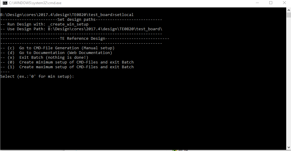
_create_win_setup.cmd/_create_linux_setup.sh and follow instructions on shell:
Code Block language bash theme Midnight title _create_win_setup.cmd/_create_linux_setup.sh ------------------------Set design paths---------------------------- -- Run Design with: _create_win_setup -- Use Design Path: <absolute project path> -------------------------------------------------------------------- -------------------------TE Reference Design--------------------------- -------------------------------------------------------------------- -- (0) Module selection guide, project creation...prebuilt export... -- (1) Create minimum setup of CMD-Files and exit Batch -- (2) Create maximum setup of CMD-Files and exit Batch -- (3) (internal only) Dev -- (4) (internal only) Prod -- (c) Go to CMD-File Generation (Manual setup) -- (d) Go to Documentation (Web Documentation) -- (g) Install Board Files from Xilinx Board Store (beta) -- (a) Start design with unsupported Vivado Version (beta) -- (x) Exit Batch (nothing is done!) ---- Select (ex.:'0' for module selection guide):- Press 0 and enter to start "Module Selection Guide"
- Createproject and follow instructions of the product selection guide, settings file will be configured automatically during this process.
optional for manual changes: Select correct device and Xilinx install path on "design_basic_settings.cmd" and create Vivado project with "vivado_create_project_guimode.cmd"
Note Note: Select correct one, see also Vivado Board Part Flow
Create hardware description file (.xsa file) for PetaLinux project and export to prebuilt folder
Code Block language py theme Midnight title run on Vivado TCL (Script generates design and export files into "<project folder>\prebuilt\hardware\<short name>") TE::hw_build_design -export_prebuiltInfo Using Vivado GUI is the same, except file export to prebuilt folder.
- Create and configure your PetaLinux project with exported .xsa-file, see PetaLinux KICKstart
- use TE Template from "<project folder>\os\petalinux"
use exported .xsa file from "<project folder>\prebuilt\hardware\<short name>" . Note: HW Export from Vivado GUI creates another path as default workspace.
- Configure the boot.scr file as needed, see Distro Boot with Boot.scr
- Generate Programming Files with Vitis
- Copy PetaLinux build image files to prebuilt folder
- copy u-boot.elf, system.dtb, bl31.elf, image.ub and boot.scr from "<plnx-proj-root>/images/linux" to prebuilt folder
Info "<project folder>\prebuilt\os\petalinux\<ddr size>" or "<project folder>\prebuilt\os\petalinux\<short name>"
Page properties hidden true id Comments This step depends on Xilinx Device/Hardware
for Zynq-7000 series
- copy u-boot.elf, system.dtb, image.ub and boot.scr from "<plnx-proj-root>/images/linux" to prebuilt folder
for ZynqMP
- copy u-boot.elf, system.dtb, bl31.elf, image.ub and boot.scr from "<plnx-proj-root>/images/linux" to prebuilt folder
for Microblaze
- ...
- copy u-boot.elf, system.dtb, bl31.elf, image.ub and boot.scr from "<plnx-proj-root>/images/linux" to prebuilt folder
- Generate Programming Files
Code Block language py theme Midnight title run on Vivado TCL (Script generates applications and bootable files, which are defined in "test_board\sw_lib\apps_list.csv") TE::sw_run_vitis -all TE::sw_run_vitis (optional; Start Vitis from Vivado GUI or start with TE Scripts on Vivado TCL)Note TCL scripts generate also platform project, this must be done manually in case GUI is used. See Vitis
- Copy PetaLinux build image files to prebuilt folder
- Generate Programming Files with Petalinux (alternative), see PetaLinux KICKstart
Launch
| Scroll Ignore | ||||||||||||||
|---|---|---|---|---|---|---|---|---|---|---|---|---|---|---|
| ||||||||||||||
| Page properties | ||||
|---|---|---|---|---|
| ||||
Note:
|
Programming
| Note |
|---|
Check Module and Carrier TRMs for proper HW configuration before you try any design. |
Xilinx documentation for programming and debugging: Vivado/Vitis/SDSoC-Xilinx Software Programming and Debugging
Note: Depending on CPLD Firmware and Boot Mode settings, QSPI boot with Linux image on SD or complete SD Boot is possible.
Get prebuilt boot binaries
- _create_win_setup.cmd/_create_linux_setup.sh and follow instructions on shell:
- Press 0 and enter to start "Module Selection Guide"
- Select assembly version
- Validate selection
Select create and open delivery binary folder
Info Note: Folder "<project folder>/_binaries_<Article Name>" with subfolder "boot_<app name>" for different applications will be generated
QSPI-Boot mode
Option for Boot.bin on QSPI Flash and image.ub, and boot.scr on SD or USB.
- Connect JTAG and power on carrier with module
Open Vivado Project with "vivado_open_existing_project_guimode.cmd" or if not created, create with "vivado_create_project_guimode.cmd"
Code Block language py theme Midnight title run on Vivado TCL (Script programs BOOT.bin on QSPI flash) TE::pr_program_flash -swapp u-boot TE::pr_program_flash -swapp hello_te0820 (optional)Note To program with Vitis/Vivado GUI, use special FSBL (fsbl_flash) on setup
- Copy image.ub, and boot.scr on SD or USB
- use files from "<project folder>\_binaries_<Article Name>\boot_linux" from generated binary folder,see: Get prebuilt boot binaries
- or use prebuilt file location, see "<project folder>\prebuilt\file_location.txt"
- Set Boot Mode to QSPI-Boot and insert SD or USB.
- Depends on Carrier, see carrier TRM.
SD-Boot mode
- Copy image.ub, boot.src and Boot.bin on SD
- use files from "<project folder>\_binaries_<Article Name>\boot_linux" from generated binary folder, see: Get prebuilt boot binaries
- or use prebuilt file location, see "<project folder>\prebuilt\file_location.txt"
- Set Boot Mode to SD-Boot.
- Depends on Carrier, see carrier TRM.
- Insert SD-Card in SD-Slot.
JTAG
Not used on this example.
Usage
- Prepare HW like described on section Programming
- Connect UART USB (most cases same as JTAG)
Select SD Card as Boot Mode (or QSPI - depending on step 1)
Info Note: See TRM of the Carrier, which is used.
Tip Starting with Petalinux version 2020.1, the industry standard "Distro-Boot" boot flow for U-Boot was introduced, which significantly expands the possibilities of the boot process and has the primary goal of making booting much more standardised and predictable.
The boot options described above describe the common boot processes for this hardware; other boot options are possible.
For more information see Distro Boot with Boot.scrPower On PCB
Expand title boot process 1. ZynqMP Boot ROM loads FSBL from SD/QSPI into OCM,
2. FSBL init the PS, programs the PL using the bitstream and loads PMU, ATF and U-boot from SD/QSPI into DDR,
3. U-boot loads Linux (image.ub) from SD/QSPI/... into DDR
Page properties hidden true id Comments This step depends on Xilinx Device/Hardware
for Zynq-7000 series
1. Zynq Boot ROM loads FSBL from SD/QSPI into OCM,
2. FSBL init the PS, programs the PL using the bitstream and loads U-boot from SD/QSPI into DDR,
3. U-boot loads Linux (image.ub) from SD/QSPI/... into DDR
for ZynqMP???
1. ZynqMP Boot ROM loads FSBL from SD/QSPI into OCM,
2. FSBL init the PS, programs the PL using the bitstream and loads PMU, ATF and U-boot from SD/QSPI into DDR,
3. U-boot loads Linux (image.ub) from SD/QSPI/... into DDR
for Microblaze with Linux
1. FPGA Loads Bitfile from Flash,
2. MCS Firmware configure SI5338 and starts Microblaze, (only if mcs is available)
3. SREC Bootloader from Bitfile Firmware loads U-Boot into DDR (This takes a while),
4. U-boot loads Linux from QSPI Flash into DDR
for native FPGA
...
Linux
- Open Serial Console (e.g. putty)
- Speed: 115200
select COM Port
Info Win OS, see device manager, Linux OS see dmesg |grep tty (UART is *USB1)
Linux Console:
Info Note: Wait until Linux boot finished
You can use Linux shell now.
Code Block language bash theme Midnight i2cdetect -y -r 0 (check I2C 0 Bus) dmesg | grep rtc (RTC check) udhcpc (ETH0 check) lsusb (USB check)Option Features
- Webserver to get access to Zynq
- insert IP on web browser to start web interface
- init.sh scripts
- add init.sh script on SD, content will be load automatically on startup (template included in "<project folder>\misc\SD")
- Webserver to get access to Zynq
Vivado HW Manager
| Page properties | ||||
|---|---|---|---|---|
| ||||
Note:
|
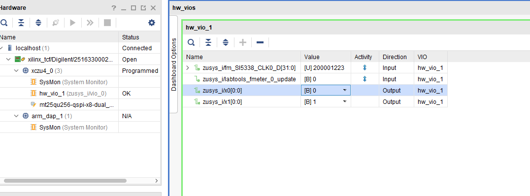
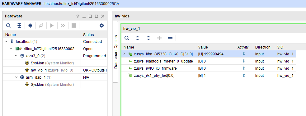
Open Vivado HW-Manager and add VIO signal to dashboard (*.ltx located on prebuilt folder)
- Control:
- User LED (PCB REV03 and newer)
- User LED (PCB REV03 and newer)
- Monitoring:
- SI5338_CLK0 Counter:
- Set radix from VIO signals to unsigned integer.
Note: Frequency Counter is inaccurate and displayed unit is Hz - SI5338 CLK is configured to 200MHz by default.
- Set radix from VIO signals to unsigned integer.
- SI5338_CLK0 Counter:
PCB REV03 Design:
- User LED, see: TE0820 CPLD#LED
| Scroll Title | ||||||
|---|---|---|---|---|---|---|
| ||||||
 |
System Design - Vivado
| Scroll Ignore | ||||||||||||||
|---|---|---|---|---|---|---|---|---|---|---|---|---|---|---|
| ||||||||||||||
| Page properties | ||||
|---|---|---|---|---|
| ||||
Note:
|
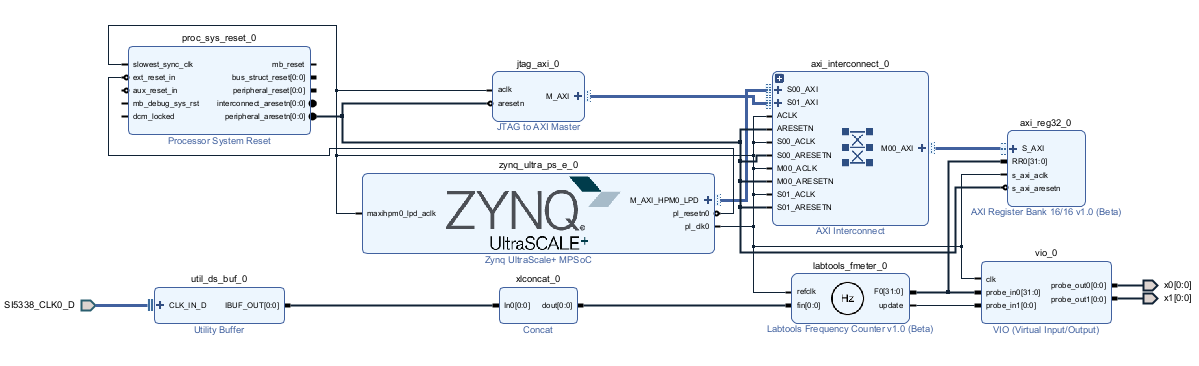
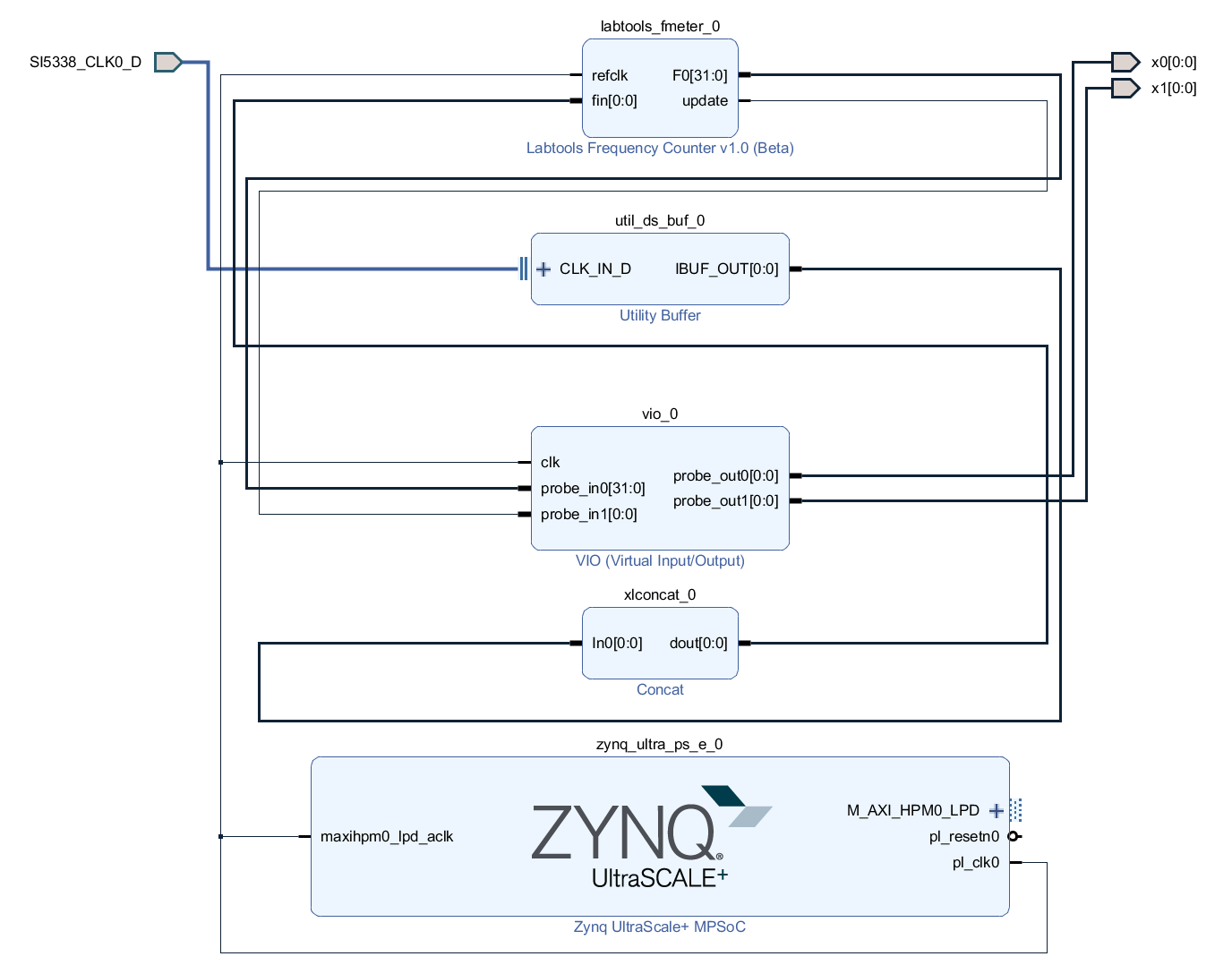
Block Design
PCB REV03
| Scroll Title | ||||||
|---|---|---|---|---|---|---|
| ||||||
|
PS Interfaces
Activated interfaces:
| Type | Note |
|---|---|
| DDR | |
| QSPI | MIO |
| SD0 | MIO |
| SD1 | MIO |
| I2C0 | MIO |
| UART0 | MIO |
| GPIO0 | MIO |
| SWDT0..1 | |
| TTC0..3 | |
| GEM3 | MIO |
| USB0 | MIO, USB2 only |
Constrains
Basic module constrains
| Code Block | ||||
|---|---|---|---|---|
| ||||
set_property BITSTREAM.GENERAL.COMPRESS TRUE [current_design]
set_property BITSTREAM.CONFIG.UNUSEDPIN PULLNONE [current_design |
Design specific constrain
| Code Block | ||||
|---|---|---|---|---|
| ||||
set_property PACKAGE_PIN K9 [get_ports {SI5338_CLK0_D_clk_p[0]}]
set_property IOSTANDARD LVDS [get_ports {SI5338_CLK0_D_clk_p[0]}]
set_property DIFF_TERM TRUE [get_ports {SI5338_CLK0_D_clk_p[0]}]

set_property PACKAGE_PIN H1 [get_ports {x0[0]}]
set_property IOSTANDARD LVCMOS18 [get_ports {x0[0]}]
set_property PACKAGE_PIN J1 [get_ports {x1[0]}]
set_property IOSTANDARD LVCMOS18 [get_ports {x1[0]}] |
Software Design - Vitis
| Scroll Ignore | ||||||||||||||
|---|---|---|---|---|---|---|---|---|---|---|---|---|---|---|
| ||||||||||||||
| Page properties | ||||
|---|---|---|---|---|
| ||||
Note:
|
For Vitis project creation, follow instructions from:
Application
| Page properties | ||||
|---|---|---|---|---|
| ||||
---------------------------------------------------------- FPGA Example ---------------------------------------------------------- scuMCS Firmware to configure SI5338 and Reset System. srec_spi_bootloaderTE modified 2023.2 SREC Bootloader to load app or second bootloader from flash into DDR Descriptions:
xilisf_v5_11TE modified 2023.2 xilisf_v5_11
---------------------------------------------------------- Zynq Example: ---------------------------------------------------------- fsblTE modified 2023.2 FSBL General:
Module Specific:
---------------------------------------------------------- ZynqMP Example: ---------------------------------------------------------- zynqmp_fsblTE modified 2023.2 FSBL General:
Module Specific:
zynqmp_pmufwXilinx default PMU firmware. ---------------------------------------------------------- General Example: ---------------------------------------------------------- hello_te0820Hello TE0820 is a Xilinx Hello World example as endless loop instead of one console output. u-bootU-Boot.elf is generated with PetaLinux. Vitis is used to generate Boot.bin. |
zynqmp_fsbl
TE modified 2023.2 FSBL
General:
- Modified Files: xfsbl_main.c, xfsbl_hooks.h/.c, xfsbl_board.h/.c (search for 'TE Mod' on source code)
- Add Files: te_xfsbl_hooks.h/.c (for hooks and board)
- General Changes:
- Display FSBL Banner and Device Name
Module Specific:
- Add Files: all TE Files start with te_*
- Si5338 Configuration
- ETH+OTG Reset over MIO
zynqmp_pmufw
Xilinx default PMU firmware.
hello_te0820
Hello TE0820 is a Xilinx Hello World example as endless loop instead of one console output.
u-boot
U-Boot.elf is generated with PetaLinux. Vitis is used to generate Boot.bin.
Software Design - PetaLinux
| Scroll Ignore | ||||||||||||||
|---|---|---|---|---|---|---|---|---|---|---|---|---|---|---|
| ||||||||||||||
| Page properties | ||||
|---|---|---|---|---|
| ||||
Note:
|
For PetaLinux installation and project creation, follow instructions from:
Config
Start with petalinux-config or petalinux-config --get-hw-description
Changes:
- select SD default instead of eMMC:
- CONFIG_SUBSYSTEM_PRIMARY_SD_PSU_SD_1_SELECT=y
- add new flash partition for bootscr and sizing
- CONFIG_SUBSYSTEM_FLASH_PSU_QSPI_0_BANKLESS_PART0_SIZE=0xA00000
- CONFIG_SUBSYSTEM_FLASH_PSU_QSPI_0_BANKLESS_PART1_SIZE=0x2000000
- CONFIG_SUBSYSTEM_FLASH_PSU_QSPI_0_BANKLESS_PART2_SIZE=0x40000
- CONFIG_SUBSYSTEM_FLASH_PSU_QSPI_0_BANKLESS_PART3_NAME="bootscr"
- CONFIG_SUBSYSTEM_FLASH_PSU_QSPI_0_BANKLESS_PART3_SIZE=0x80000
- Identification
- CONFIG_SUBSYSTEM_HOSTNAME="Trenz"
- CONFIG_SUBSYSTEM_PRODUCT="TE0820"
U-Boot
Start with petalinux-config -c u-boot
Changes:
- MAC from eeprom together with uboot and device tree settings:
- CONFIG_ENV_OVERWRITE=y
- CONFIG_NVMEM=y
- CONFIG_DM_RTC=y (needed for nvmem driver because of bug in uboot)
- Boot Modes:
- CONFIG_QSPI_BOOT=y
- CONFIG_SD_BOOT=y
- CONFIG_ENV_IS_IN_FAT is not set
- CONFIG_ENV_IS_IN_NAND is not set
- CONFIG_ENV_IS_IN_SPI_FLASH is not set
- CONFIG_BOOT_SCRIPT_OFFSET=0x2A40000
- Identification
- CONFIG_IDENT_STRING=" TE0820"
Change platform-top.h:
| Code Block | ||
|---|---|---|
| ||
#include <configs/xilinx_zynqmp.h> #no changes |
Device Tree
| Code Block | ||||
|---|---|---|---|---|
| ||||
/include/ "system-conf.dtsi"
/*-------------------- SD0 eMMC ----------------*/
&sdhci0 {
// disable-wp;
no-1-8-v;
};
/*-------------------- SD1 sd2.0 ----------------*/
&sdhci1 {
disable-wp;
no-1-8-v;
};
/*-------------------- USB 2.0 only ----------------*/
&usb0 {
status = "okay";
clock-names = "bus_clk";
clocks = <&zynqmp_clk USB0_BUS_REF>;
assigned-clocks = <&zynqmp_clk USB0_BUS_REF>;
};
&dwc3_0 {
dr_mode = "host";
};
/*------------------ ETH PHY --------------------*/
&gem3 {
//required otherwise petalinux gives a static address here
/delete-property/ local-mac-address;
phy-handle = <&phy0>;
nvmem-cells = <ð0_addr>;
nvmem-cell-names = "mac-address";
phy0: phy0@1 {
device_type = "ethernet-phy";
reg = <1>;
};
};
/*------------------ QSPI -------------------- */
&qspi {
#address-cells = <1>;
#size-cells = <0>;
status = "okay";
flash0: flash@0 {
compatible = "jedec,spi-nor";
reg = <0x0>;
#address-cells = <1>;
#size-cells = <1>;
spi-rx-bus-width = <4>;
spi-tx-bus-width = <4>;
spi-max-frequency = <90000000>;
};
};
/*------------------ I2C --------------------*/
&i2c0 {
eeprom: eeprom@50 {
compatible = "microchip,24aa025", "atmel,24c02";
reg = <0x50>;
#address-cells = <1>;
#size-cells = <1>;
eth0_addr: eth-mac-addr@FA {
reg = <0xFA 0x06>;
};
};
};
|
Kernel
Start with petalinux-config -c kernel
Changes:
Only needed to fix JTAG Debug issue:
CONFIG_CPU_FREQ is not set
Rootfs
Start with petalinux-config -c rootfs
Changes:
- for web server app:
- CONFIG_busybox-httpd=y
- For additional test tools only:
- CONFIG_i2c-tools=y
- CONFIG_packagegroup-petalinux-utils(util-linux,cpufrequtils,bridge-utils,mtd-utils,usbutils,pciutils,canutils,i2c-tools,smartmontools,e2fsprogs)
- For auto login:
- CONFIG_imagefeature-serial-autologin-root=y
FSBL patch (alternative for vitis fsbl trenz patch)
See "<project folder>\os\petalinux\project-spec\meta-user\recipes-bsp\embeddedsw"
Petalinux Troubleshoot#Petalinux2023.2
Applications
See "<project folder>\os\petalinux\project-spec\meta-user\recipes-apps\"
startup
Script App to load init.sh from SD Card if available.webfwu
Webserver application suitable for Zynq access. Need busybox-httpd
Additional Software
| Scroll Ignore | ||||||||||||||
|---|---|---|---|---|---|---|---|---|---|---|---|---|---|---|
| ||||||||||||||
| Page properties | ||||
|---|---|---|---|---|
| ||||
| Note: |
SI5338
File location "<project folder>\misc\Si5338\Si5338-*.slabtimeproj"
General documentation how you work with these project will be available on Si5338
Appx. A: Change History and Legal Notices
| Scroll Ignore | ||||||||||||||
|---|---|---|---|---|---|---|---|---|---|---|---|---|---|---|
| ||||||||||||||
Document Change History
To get content of older revision got to "Change History" of this page and select older document revision number.
| Page properties | ||||
|---|---|---|---|---|
| ||||
|
| Scroll Title | |||||||||||||||||||||||||||||||||||||||||||||||||||||||||||||||||||||||||||||||||||||||||||||||||||||||||||||||||||||||||||||||||||||||||||||||||||||||||||||||||||
|---|---|---|---|---|---|---|---|---|---|---|---|---|---|---|---|---|---|---|---|---|---|---|---|---|---|---|---|---|---|---|---|---|---|---|---|---|---|---|---|---|---|---|---|---|---|---|---|---|---|---|---|---|---|---|---|---|---|---|---|---|---|---|---|---|---|---|---|---|---|---|---|---|---|---|---|---|---|---|---|---|---|---|---|---|---|---|---|---|---|---|---|---|---|---|---|---|---|---|---|---|---|---|---|---|---|---|---|---|---|---|---|---|---|---|---|---|---|---|---|---|---|---|---|---|---|---|---|---|---|---|---|---|---|---|---|---|---|---|---|---|---|---|---|---|---|---|---|---|---|---|---|---|---|---|---|---|---|---|---|---|---|---|---|
| |||||||||||||||||||||||||||||||||||||||||||||||||||||||||||||||||||||||||||||||||||||||||||||||||||||||||||||||||||||||||||||||||||||||||||||||||||||||||||||||||||
|
| HTML |
|---|
<!--
Template Revision 1.0
Basic Notes
 - export PDF to download, if vivado revision is changed!
 - Template is for different design and SDSoC and examples, remove unused or wrong description!
--> |
| Scroll Only (inline) |
|---|
Online version of this manual and other related documents can be found at https://wiki.trenz-electronic.de/display/PD/Trenz+Electronic+Documentation |
| Scroll pdf ignore | ||||
|---|---|---|---|---|
Table of contents
|
Overview
| HTML |
|---|
<!--
General Design description
--> |
ZynqMP PS Design with Linux Example and simple frequency counter to measure SI5338 Reference CLK with Vivado HW-Manager.
Key Features
| HTML |
|---|
<!--
Add Basic Key Features of the design (should be tested)
--> |
| Excerpt |
|---|
|
Revision History
| HTML |
|---|
<!--
- Add changes from design
- Export PDF to download, if vivado revision is changed!
--> |
...
- differnent Design for REV03
- smal petalinux changes
- IO Renaming
- additional notes FSBL generated with Win SDK
- changed *.bif
...
- bugfix board part files BANK1 MIO voltages
- Add "dummy" PS USB3 parameter so solve problems with some USB2 devices
...
TE0820-test_board-vivado_2017.4-build_10_20180524151356.zip
TE0820-test_board_noprebuilt-vivado_2017.4-build_10_20180524151342.zip
...
- solved Linux Flash issue
- new assembly variant
...
- new assembly variants
...
- solved JTAG/Linux issue
...
- board part csv update
...
- rework board part files
- solved USB, QSPI and PHy issue
...
- solved SD SDX Cards Problem
- Separate csv name for all assembly variants
...
- solved SD WP Problem
...
- initial release
Release Notes and Know Issues
| HTML |
|---|
<!--
- add known Design issues and general Notes for the current revision
--> |
...
Do not use HW Manager connection, or if debugging is nessecary:
- Boot linux with usb terminal
- From the terminal: root root mount ifconfig eth0
- Open two new SSH terminals via ethernet: root root , run user application ...
- Exit and close the usb terminal
...
Requirements
Software
| HTML |
|---|
<!--
Add needed external Software
--> |
...
Hardware
| HTML |
|---|
<!--
Hardware Support
--> |
Basic description of TE Board Part Files is available on TE Board Part Files.
Complete List is available on <design name>/board_files/*_board_files.csv
Design supports following modules:
...
- use slower DDR speed
...
TE0820-02-2CG-1E
...
Design supports following carriers:
...
- Important: See restrictions on usage with 7 Serie Carriers: 4 x 5 SoM Carriers
...
- Important: See restrictions on usage with 7 Serie Carriers: 4 x 5 cm carriers
- Used as reference carrier.
...
- Important: See restrictions on usage with 7 Serie Carriers: 4 x 5 SoM Carriers
...
- Important: See restrictions on usage with 7 Serie Carriers: 4 x 5 SoM Carriers
...
- Important: See restrictions on usage with 7 Serie Carriers: 4 x 5 SoM Carriers
- No SD Slot available, pins goes to Pin Header
- For TEBA0841 REV01, please contact TE support
Additional HW Requirements:
...
Content
| HTML |
|---|
<!--
Remove unused content
--> |
For general structure and of the reference design, see Project Delivery
Design Sources
...
Additional Sources
...
Prebuilt
| HTML |
|---|
<!--

<table width="100%">
<tr> <th>File                                 </th> <th>File-Extension</th>  <th>Description                                                                              </th> </tr>
<tr> <td>BIF-File                             </td> <td>*.bif         </td>  <td>File with description to generate Bin-File                                               </td> </tr>
<tr> <td>BIN-File                             </td> <td>*.bin         </td>  <td>Flash Configuration File with Boot-Image (Zynq-FPGAs)                                    </td> </tr>
<tr> <td>BIT-File                             </td> <td>*.bit         </td>  <td>FPGA Configuration File                                                                  </td> </tr>
<tr> <td>DebugProbes-File                     </td> <td>*.ltx         </td>  <td>Definition File for Vivado/Vivado Labtools Debugging Interface                           </td> </tr>
<tr> <td>Debian SD-Image                      </td> <td>*.img         </td>  <td>Debian Image for SD-Card                                                                </td> </tr>
<tr> <td>Diverse Reports                      </td> <td>  ---         </td>  <td>Report files in different formats                                                        </td> </tr>
<tr> <td>Hardware-Platform-Specification-Files</td> <td>*.hdf         </td>  <td>Exported Vivado Hardware Specification for SDK/HSI                                       </td> </tr>
<tr> <td>LabTools Project-File                </td> <td>*.lpr         </td>  <td>Vivado Labtools Project File                                                             </td> </tr>
<tr> <td>MCS-File                             </td> <td>*.mcs         </td>  <td>Flash Configuration File with Boot-Image (MicroBlaze or FPGA part only)                  </td> </tr>
<tr> <td>MMI-File                             </td> <td>*.mmi         </td>  <td>File with BRAM-Location to generate MCS or BIT-File with *.elf content (MicroBlaze only) </td> </tr>
<tr> <td>OS-Image                             </td> <td>*.ub          </td>  <td>Image with Linux Kernel (On Petalinux optional with Devicetree and RAM-Disk)             </td> </tr>
<tr> <td>Software-Application-File            </td> <td>*.elf         </td>  <td>Software Application for Zynq or MicroBlaze Processor Systems                            </td> </tr>
<tr> <td>SREC-File                            </td> <td>*.srec        </td>  <td>Converted Software Application for MicroBlaze Processor Systems                          </td> </tr>
</table>
-->
|
...
File
...
File-Extension
...
Description
...
Download
Reference Design is only usable with the specified Vivado/SDK/PetaLinux/SDx version. Do never use different Versions of Xilinx Software for the same Project.
| HTML |
|---|
<!--
Add correct path:https://shop.trenz-electronic.de/en/Download/?path=Trenz_Electronic/TE0803/Reference_Design/2017.1/Starterkit
--> |
Reference Design is available on:
Design Flow
| HTML |
|---|
<!--
Basic Design Steps
Add/ Remove project specific
--> |
| Note |
|---|
Reference Design is available with and without prebuilt files. It's recommended to use TE prebuilt files for first launch. |
Trenz Electronic provides a tcl based built environment based on Xilinx Design Flow.
See also:
The Trenz Electronic FPGA Reference Designs are TCL-script based project. Command files for execution will be generated with "_create_win_setup.cmd" on Windows OS and "_create_linux_setup.sh" on Linux OS.
TE Scripts are only needed to generate the vivado project, all other additional steps are optional and can also executed by Xilinx Vivado/SDK GUI. For currently Scripts limitations on Win and Linux OS see: Project Delivery Currently limitations of functionality
- _create_win_setup.cmd/_create_linux_setup.sh and follow instructions on shell:
- Press 0 and enter for minimum setup
- (optional Win OS) Generate Virtual Drive or use short directory for the reference design (for example x:\<design name>)
- Create Project
- Select correct device and Xilinx install path on "design_basic_settings.cmd" and create Vivado project with "vivado_create_project_guimode.cmd"
Note: Select correct one, see TE Board Part Files
- Select correct device and Xilinx install path on "design_basic_settings.cmd" and create Vivado project with "vivado_create_project_guimode.cmd"
- Create HDF and export to prebuilt folder
- Run on Vivado TCL: TE::hw_build_design -export_prebuilt
Note: Script generate design and export files into \prebuilt\hardware\<short dir>. Use GUI is the same, except file export to prebuilt folder
- Run on Vivado TCL: TE::hw_build_design -export_prebuilt
- Create Linux (bl31.elf, uboot.elf and image.ub) with exported HDF
- HDF is exported to "prebuilt\hardware\<short name>"
Note: HW Export from Vivado GUI create another path as default workspace. - Create Linux images on VM, see PetaLinux KICKstart
- Use TE Template from /os/petalinux
Note: run init_config.sh before you start petalinux config. This will set correct temporary path variable.
- Use TE Template from /os/petalinux
- HDF is exported to "prebuilt\hardware\<short name>"
- Add Linux files (bl31.elf, uboot.elf and image.ub) to prebuilt folder
- "prebuilt\os\petalinux\default" or "prebuilt\os\petalinux\<short name>"
Notes: Scripts select "prebuilt\os\petalinux\<short name>", if exist, otherwise "prebuilt\os\petalinux\default"
- "prebuilt\os\petalinux\default" or "prebuilt\os\petalinux\<short name>"
- Generate Programming Files with HSI/SDK
- Run on Vivado TCL: TE::sw_run_hsi
Note: Scripts generate applications and bootable files, which are defined in "sw_lib\apps_list.csv" - (alternative) Start SDK with Vivado GUI or start with TE Scripts on Vivado TCL: TE::sw_run_sdk
Note: See SDK Projects
- Run on Vivado TCL: TE::sw_run_hsi
Launch
Programming
| HTML |
|---|
<!--
Description of Block Design, Constrains...
BD Pictures from Export...
--> |
| Note |
|---|
Check Module and Carrier TRMs for proper HW configuration before you try any design. |
Xilinx documentation for programming and debugging: Vivado/SDK/SDSoC-Xilinx Software Programming and Debugging
Note: Depending on CPLD Firmware and Boot Mode settings, QSPI boot with Linux image on SD or complete SD Boot is possible.
QSPI
Optional for Boot.bin on QSPI Flash and image.ub on SD.
- Connect JTAG and power on carrier with module
- Open Vivado Project with "vivado_open_existing_project_guimode.cmd" or if not created, create with "vivado_create_project_guimode.cmd"
- Type on Vivado TCL Console: TE::pr_program_flash_binfile -swapp u-boot
Note: To program with SDK/Vivado GUI, use special FSBL (zynqmp_fsbl_flash) on setup
optional "TE::pr_program_flash_binfile -swapp hello_te0820" possible - Copy image.ub on SD-Card
- For correct prebuilt file location, see <design_name>/prebuilt/readme_file_location.txt
- Insert SD-Card
SD
Use this description for CPLD Firmware with SD Boot selectable.
- Copy image.ub and Boot.bin on SD-Card.
- For correct prebuilt file location, see <design_name>/prebuilt/readme_file_location.txt
- Insert SD-Card in SD-Slot.
JTAG
Not used on this Example.
Usage
- Prepare HW like described on section Programming
- Connect UART USB (most cases same as JTAG)
- Select SD Card or QSPI as Boot Mode (Depends on used programming variant)
Note: See TRM of the Carrier, which is used. - Power On PCB
Note: 1. ZynqMP Boot ROM loads PMU Firmware and FSBL from SD/QSPI Flash into OCM, 2. FSBL loads ATF(bl31.elf) and U-boot from SD into DDR, 3. U-boot load Linux from SD into DDR
Linux
- Open Serial Console (e.g. putty)
- Speed: 115200
- COM Port: Win OS, see device manager, Linux OS see dmesg |grep tty (UART is *USB1)
- Linux Console:
Note: Wait until Linux boot finished For Linux Login use:- User Name: root
- Password: root
- You can use Linux shell now.
- I2C 0 Bus type: i2cdetect -y -r 0
- RTC check: dmesg | grep rtc
- ETH0 works with udhcpc
- USB type "lsusb" or connect USB2.0 device
Vivado HW Manager
SI5338_CLK0 Counter:
- Open Vivado HW-Manager and add VIO signal to dashboard (*.ltx located on prebuilt folder).
- Set radix from VIO signals to unsigned integer.
Note: Frequency Counter is inaccurate and displayed unit is Hz
- Set radix from VIO signals to unsigned integer.
SI5338 CLK is configured to 200MHz by default.
PCB REV03 Design:
- User LED, see: TE0820 CPLD#LED
PCB REV01, REV02 Design:
- PHY LEDS, see: TE0820-REV01_REV02 CPLD#X0/X1Pin
- CPLD Firmware, see: TE0820-REV01_REV02 CPLD#X0/X1Pin
System Design - Vivado
| HTML |
|---|
<!--
Description of Block Design, Constrains...
BD Pictures from Export...
--> |
Block Design
PCB REV03
PCB REV01 REV02
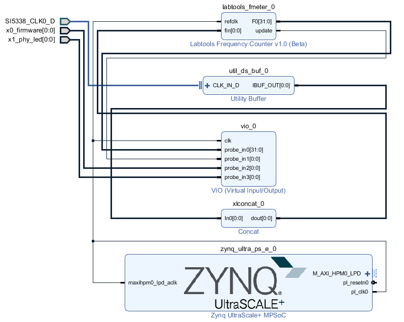
PS Interfaces
Activated interfaces:
...
Constrains
Basic module constrains
| Code Block | ||||
|---|---|---|---|---|
| ||||
set_property BITSTREAM.GENERAL.COMPRESS TRUE [current_design]
set_property BITSTREAM.CONFIG.UNUSEDPIN PULLNONE [current_design |
Design specific constrain
| Code Block | ||||
|---|---|---|---|---|
| ||||
set_property PACKAGE_PIN K9 [get_ports {SI5338_CLK0_D_clk_p[0]}]
set_property IOSTANDARD LVDS [get_ports {SI5338_CLK0_D_clk_p[0]}]
set_property DIFF_TERM TRUE [get_ports {SI5338_CLK0_D_clk_p[0]}]

set_property PACKAGE_PIN H1 [get_ports {x0[0]}]
set_property IOSTANDARD LVCMOS18 [get_ports {x0[0]}]
set_property PACKAGE_PIN J1 [get_ports {x1[0]}]
set_property IOSTANDARD LVCMOS18 [get_ports {x1[0]}] |
Software Design - SDK/HSI
| HTML |
|---|
<!--
optional chapter
separate sections for different apps
--> |
For SDK project creation, follow instructions from:
Application
zynqmp_fsbl
TE modified 2018.2 FSBL
Changes:
- Si5338 Configuration, ETH+OTG Reset over GPIO
- see xfsbl_board.c, xfsbl_board.h, xfsbl_main.c
- Add register_map.h, si5338.c, si5338.h
Note: Remove compiler flags "-Os -flto -ffat-lto-objects" if you create 2018.2 FSBL with SDK
zynqmp_fsbl_flash
TE modified 2017.4 FSBL
Changes:
- Set FSBL Boot Mode to JTAG
- Disable Memory initialisation
- see xfsbl_initialisation.c, xfsbl_hw.h, xfsbl_handoff.c, xfsbl_main.c
Note: Remove compiler flags "-Os -flto -ffat-lto-objects" if you create 2018.2 FSBL with SDK
zynqmp_pmufw
Xilinx default PMU firmware.
Hello TE0820
Hello TE0820 is a Xilinx Hello World example as endless loop instead of one console output.
U-Boot
U-Boot.elf is generated with PetaLinux. SDK/HSI is used to generate Boot.bin.
Software Design - PetaLinux
| HTML |
|---|
<!--
optional chapter
Add "No changes." or "Activate: List"
--> |
For PetaLinux installation and project creation, follow instructions from:
Config
Activate:
- SUBSYSTEM_PRIMARY_SD_PSU_SD_1_SELECT
U-Boot
- Change platform-top.h
| Code Block | ||
|---|---|---|
| ||
#include <configs/platform-auto.h>
#define CONFIG_SYS_BOOTM_LEN 0xF000000

#define DFU_ALT_INFO_RAM \
                "dfu_ram_info=" \
        "setenv dfu_alt_info " \
        "image.ub ram $netstart 0x1e00000\0" \
        "dfu_ram=run dfu_ram_info && dfu 0 ram 0\0" \
        "thor_ram=run dfu_ram_info && thordown 0 ram 0\0"

#define DFU_ALT_INFO_MMC \
        "dfu_mmc_info=" \
        "set dfu_alt_info " \
        "${kernel_image} fat 0 1\\\\;" \
        "dfu_mmc=run dfu_mmc_info && dfu 0 mmc 0\0" \
        "thor_mmc=run dfu_mmc_info && thordown 0 mmc 0\0"

/*Required for uartless designs */
#ifndef CONFIG_BAUDRATE
#define CONFIG_BAUDRATE 115200
#ifdef CONFIG_DEBUG_UART
#undef CONFIG_DEBUG_UART
#endif
#endif

/*Define CONFIG_ZYNQMP_EEPROM here and its necessaries in u-boot menuconfig if you had EEPROM memory. */
#ifdef CONFIG_ZYNQMP_EEPROM
#define CONFIG_SYS_I2C_EEPROM_ADDR_LEN  1
#define CONFIG_CMD_EEPROM
#define CONFIG_ZYNQ_EEPROM_BUS          5
#define CONFIG_ZYNQ_GEM_EEPROM_ADDR     0x54
#define CONFIG_ZYNQ_GEM_I2C_MAC_OFFSET  0x20
#endif
|
Device Tree
| Code Block | ||
|---|---|---|
| ||
/include/ "system-conf.dtsi"
/ {
};


/* SDIO */

&sdhci1 {
   disable-wp;
   no-1-8-v;
};

/* ETH PHY */
&gem3 {

    status = "okay";
  ethernet_phy0: ethernet-phy@0 {
        compatible = "marvell,88e1510";
        device_type = "ethernet-phy";
            reg = <1>;
    };
};
/* USB 2.0 */

&dwc3_0 {
    status = "okay";
    dr_mode = "host";
    maximum-speed = "high-speed";
    /delete-property/phy-names;
    /delete-property/phys;
    /delete-property/snps,usb3_lpm_capable;
};

/* QSPI PHY */
&qspi {
    #address-cells = <1>;
    #size-cells = <0>;
    status = "okay";
    flash0: flash@0 {
        compatible = "jedec,spi-nor";
        reg = <0x0>;
        #address-cells = <1>;
        #size-cells = <1>;
    };
};

/* DMA not used: Reduce error messages on linux.*/

&lpd_dma_chan1 {
    status = "disabled";
};
&lpd_dma_chan2 {
    status = "disabled";
};
&lpd_dma_chan3 {
    status = "disabled";
};
&lpd_dma_chan4 {
    status = "disabled";
};
&lpd_dma_chan5 {
    status = "disabled";
};
&lpd_dma_chan6 {
    status = "disabled";
};
&lpd_dma_chan7 {
    status = "disabled";
};
&lpd_dma_chan8 {
    status = "disabled";
};
|
Kernel
Deactivate:
CONFIG_CPU_IDLE (only needed to fix JTAG Debug issue)
CONFIG_CPU_FREQ (only needed to fix JTAG Debug issue)
Rootfs
Activate:
- i2c-tools
Applications
startup
Script App to load init.sh from SD Card if available.
See: \os\petalinux\project-spec\meta-user\recipes-apps\startup\files
Additional Software
| HTML |
|---|
<!--
Add Description for other Software, for example SI CLK Builder ...
--> |
SI5338
Download ClockBuilder Desktop for SI5338
- Install and start ClockBuilder
- Select SI5338
- Options → Open register map file
Note: File location <design name>/misc/Si5338/RegisterMap.txt - Modify settings
- Options → save C code header files
- Replace Header files from FSBL template with generated file
Appx. A: Change History and Legal Notices
Document Change History
To get content of older revision got to "Change History" of this page and select older document revision number.
| HTML |
|---|
<!--
Generate new entry:
1:add new row below first
2:Copy Page Information Macro(date+user) Preview, Page Information Macro Preview
3.Update Metadate =Page Information Macro Preview+1
--> |
...
- 2018.2 release
...
...
- Design Files Update
...
Overview
Content Tools