...
- MPSoC: ZYNQ UltraScale+ ZU7EV 900-pin package
- Memory
- 64bit DDR4, 8 GByte maximum
- Dual SPI boot Flash in parallel, 512 MByte maximum - User I/Os
- 65 x PS MIOs, 48 x PL HD GPIOs, 156 x PL HP GPIOs (3 banks)
- Serial transceivers: 4 x GTR + 16 x GTH
- Transceiver clocks inputs and outputs
- PLL clock generator inputs and outputs - Si5345 - 10 output PLL
- All power supplies on board, single 3.3V power source required
- 14 on-board DC-DC regulators and 13 LDOs
- LP, FPLPD, FPD, PL separately controlled power domains - Support for all boot modes (except NAND) and scenarios
- Support for any combination of PS connected peripherals
- Size: 52 x 76 mm, 3 mm mounting holes for skyline heat spreader
- B2B connectors: 4 x 160 pin
...
| Scroll Title |
|---|
| anchor | Figure_1 |
|---|
| title | Figure 1: TE0807-01 03 block diagram |
|---|
|
| Scroll Ignore |
|---|
| draw.io Diagram |
|---|
| border | false |
|---|
| viewerToolbar | true |
|---|
| |
|---|
| fitWindow | false |
|---|
| diagramDisplayName | |
|---|
| lbox | true |
|---|
| revision | 8 |
|---|
| diagramName | TE0807-01 block diagram |
|---|
| simpleViewer | false |
|---|
| width | |
|---|
| links | auto |
|---|
| tbstyle | hidden |
|---|
| diagramWidth | 641 |
|---|
|
|
| Scroll Only |
|---|
 Image Added Image Added
|
|
Main Components
| Scroll Title |
|---|
| anchor | Figure_2 |
|---|
| title | Figure 2: TE0807-01 03 main components |
|---|
|
| Scroll Ignore |
|---|
| Scroll Only |
|---|
|
|---|
| draw.io Diagram |
|---|
| border | false |
|---|
| viewerToolbar | true |
|---|
| |
|---|
| fitWindow | false |
|---|
| diagramDisplayName | |
|---|
| lbox | true |
|---|
| revision | 3 |
|---|
| diagramName | TE0807-02 main components |
|---|
| simpleViewer | false |
|---|
| width | |
|---|
| links | auto |
|---|
| tbstyle | hidden |
|---|
| diagramWidth | 641 |
|---|
|
|
| Scroll Only |
|---|
 Image Added Image Added
|
|
- Xilinx ZYNQ UltraScale+ ZU7EV-1FBVB900 MPSoC, U1
- EN63A0QI
- Xilinx ZYNQ UltraScale+ XCZU9EG MPSoC, U1
- Low-power programmable oscillator @ 33.333333 MHz (PS_CLK), U32
- Red LED (DONE), D1
- 256Mx16 DDR4-2400 SDRAM, U12
- 256Mx16 DDR4-2400 SDRAM, U9
- 256Mx16 DDR4-2400 SDRAM, U2
- 256Mx16 DDR4-2400 SDRAM, U3
- 12A PowerSoC DC-DC converter, U4
- Quartz crystal, Y1
- TI TPS72018 LDO @1.8V, U6
- TI TPS74401 LDO @0.9V, U14
- TI TPS74401 LDO @1.2V, U28
- TI TPS72018 LDO @1.8V, U6
- Quarz Crystal @50.000MHz, Y1
- LowLow-power programmable oscillator @ 25.000000 MHz (IN0 for U5), U25
- 10-channel programmable PLL clock generator, U5
- Ultra fine 0.50 mm pitch, Razor Beam™ LP Slim Terminal Strip with 160 contacts, J4
- TI TPS74801 LDO @1.8V, U10
- TI TPS74801 LDO @0.9V, U8
- 8 Gbit (512Mx16) DDR4-2400 SDRAM, U12
- 8 Gbit (512Mx16) DDR4-2400 SDRAM, U9
- 8 Gbit (512Mx16) DDR4-2400 SDRAM, U2
- 8 Gbit (512Mx16) DDR4-2400 SDRAM, U3
- Ultra fine 0.50 mm pitch, Razor Beam™ Ultra fine 0.50 mm pitch, Razor Beam™ LP Slim Terminal Strip with 160 contacts, J2J3
- Ultra fine 0.50 mm pitch, Razor Beam™ LP Slim Terminal Strip with 160 contacts, J3J1
- Ultra fine 0.50 mm pitch, Razor Beam™ LP Slim Terminal Strip with 160 contacts, J1
- Quartz crystal, Y2
- 256 Mbit serial NOR Flash memory, U7
- J4
- Ultra fine 0.50 mm pitch, Razor Beam™ LP Slim Terminal Strip with 160 contacts, J2
- 1.8V, 512 Mbit QSPI flash memory ,U17
- 1.8V, 512 Mbit QSPI flash memory, U7
- TI TPS72018 LDO @1.8V, U27256 Mbit serial NOR Flash memory, U17
Initial Delivery State
| Storage Device Name | Content | Notes |
|---|
SPI Flash OTP Area | Empty, not programmed | Except serial number programmed by flash vendor. |
SPI Flash Quad Enable bit | Programmed | - |
SPI Flash main array | Not programmed | - |
eFUSE USER | Not programmed | - |
eFUSE Security | Not programmed | - |
| Si5345A OTP NVM | Not programmed | - |
Table 1: Initial delivery state of programmable devices on the module
...
The boot device and mode of the Zynq UltraScale+ MPSoC can be selected via 4 dedicated pins accessible on B2B connector J2:
| Boot Mode Pin | B2B Pin |
|---|
| PS_MODE0 | J2-109 |
| PS_MODE1 | J2-107 |
| PS_MODE2 | J2-105 |
| PS_MODE3 | J2-103 |
Table 2: Boot mode pins on B2B connector J2.
Following boot modes are possible on the TE0808 UltraScale+ module by generating the corresponding 4-bit code by the pins PS_MODE0 ... PS_MODE3 (little-endian alignment):
| Boot Mode | Mode Pins [3:0] | MIO Location | Description |
|---|
| JTAG | 0x0 | JTAG | Dedicated PS interface. |
| QSPI32 | 0x2 | MIO[12:0] | Configured on module with dual QSPI Flash Memory. 32-bit addressing.
Supports single and dual parallel
configurations.
Stack and dual stack is not
supported. |
| SD0 | 0x3 | MIO[25:13] | Supports SD 2.0. |
| SD1 | 0x5 | MIO[51:38] | Supports SD 2.0. |
| eMMC_18 | 0x6 | MIO[22:13] | Supports eMMC 4.5 at 1.8V. |
| USB 0 | 0x7 | MIO[52:63] | Supports USB 2.0 and USB 3.0. |
| PJTAG_0 | 0x8 | MIO[29:26] | PS JTAG connection 0 option. |
| SD1-LS | 0xE | MIO[51:39] | Supports SD 3.0 with a required SD 3.0 compliant level shifter. |
Table 3: Selectable boot modes by dedicated boot mode pins.
For functional details see ug1085 - Zynq UltraScale+ TRM (Boot Modes Section).
...
Following table lists the I/O-bank signals, which are routed from the MPSoC's PL and PS banks as LVDS pairs or single ended I/O's to the B2B connectors.
I/| Schematic Names / Connector Pins | LVDS Pairs | VCCO 24 B47_L1_P ... B47_L12_P
B47_L1_N ... B47_L12_N | pins J3-43, J3-44usable as single-ended I/OsB48_L1_P ... B48_L12_P
B48_L1_N ... B48_L12_N | 24 VCCO pins J3-15, J3-16usable as single-ended I/Os52 B64_L1_P ... B64_L24_P
B64_L1_N ... B64_L24_N B_64_T0 ... B_64_T3 | pins J4-58, J4-106usable as single |
| 65 | HP | J4 | 52 single-ended I/Os or 24 LVDS pairs |
65 | HP | J4 | B65_L1_P ... B65_L24_P
B65_L1_N ... B65_L24_N B_65_T0 ... B_65_T3 | 52 I/Os | 24 | VCCO65
pins J4-69, J4-105 | VCCO65 | VCCO max. 1.8V |
| 66 | HP | J1 | 52 single-ended I/Os or 24 LVDS pairs | VCCO66 | VCCO max. 1.8V |
usable as single-ended |
| 500 | MIO | J3 | 13 I/Os | PS_1V8 | User configurable I/Os on B2B |
| 501 |
66500 | MIO | J3 | MIO13 ... MIO25 | 13 I/Os | - | HP | J1 | B66_L1_P ... B66_L24_P
B66_L1_N ... B66_L24_N B_66_T0 ... B_66_T3 | 48 I/Os | 24 | VCCO66
pins J1-90, J1-120 | VCCO max. 1.8V
usable as single-ended I/Os | | J3 | 26 I/Os | PS_1V8 | User configurable I/Os on B2B |
| 502 | MIO | J3 | 26 I/Os |
| PS_1V8 | User configurable I/Os on B2B |
| 501 | MIO | J3 | MIO26 ... MIO51 | 26 I/Os | - | PS_1V8 | User configurable I/Os on B2B |
| 502 | MIO | J3 | MIO52 ... MIO77 | 26 I/Os | - | PS_1V8 | User configurable I/Os on B2B |
Table 4: B2B connector pin-outs of Table 4: B2B connector pin-outs of available PL and PS banks of the TE0807-01 03 SoM.
All MIO banks are powered from on-module DC-DC power rail. All PL I/O Banks have separate VCCO pins in the B2B connectors, valid VCCO should be supplied from the baseboard.
...
The Xilinx Zynq UltraScale+ MPSoC device used on the TE0807 module has 20 high-speed data lanes (Xilinx GTH / GTR transceiver). All of them are wired directly to B2B connector. MGT (Multi Gigabit Transceiver) lane consists of one transmit and one receive (TX/RX) differential pairs, four signals total per one MGT lane. Following table lists lane number, MGT bank number, transceiver type, signal schematic name, board-to-board pin connection and FPGA pins connection:
| Bank | Type | Lane | Signal Name | B2B Pin | FPGA Pin |
|---|
228B505B505B505B505JM326JM328JM325JM327PSMGTRRXP0_505 F27PSMGTRRXN0_505 F28PSMGTRTXP0_505 E25PSMGTRTXN0_505 E26B5052 | 3 | 229 | GTH | 0 | B505B505B505JM320JM322JM319JM321PSMGTRRXP1_505 D27PSMGTRRXN1_505 D28PSMGTRTXP1_505 D23PSMGTRTXN1_505, D2413 | 230 | GTH | 0 | B505_RX2_PB505_RX2_NB505B505JM314JM316JM313JM315PSMGTRRXP0_505 B27PSMGTRRXN0_505 B28PSMGTRTXP0_505 C25PSMGTRTXN0_505, C261 | 2B505128 | GTH | 0 | B505B505B505JM38JM310JM37JM39- PS_MGTRRXP1_505, A25
- PS_MGTRRXN1_505, A26
- PS_MGTRTXP1_505, B23
- PS_MGTRTXN1_505, B24
| 1 | 2 | 3 | 505 | GTR | 0 | 1 | 2 | 3 | Table 4: MGT lanes
There are 3 clock sources for the GTR transceivers. B505_CLK0 is connected directly to B2B connector JM3, so the clock can be provided by the carrier board. Clocks B505_CLK1 and B505_CLK3 are provided by the on-board clock generator (U10). As there are no capacitive coupling of the data and clock lines that are connected to the connectors, these may be required on the user’s PCB depending on the application.
...
Table 5: MGT reference clock sources
JTAG Interface
JTAG access is provided through the MPSoC's PS configuration bank 503 with bank voltage PS_1V8.
...
Table 4: B2B connector pin-out of JTAG interface.
Configuration Bank Control Signals
The Xilinx Zynq UltraScale+ MPSoC's PS configuration bank 503 control signal pins are accessible through B2B connector J2.
For further information about the particular control signals and how to use and evaluate them, refer to the Xilinx Zynq UltraScale+ MPSoC TRM and UltraScale Architecture Configuration - User Guide.
...
4-bit boot mode pins.
For further information about the boot modes refer to the Xilinx Zynq UltraScale+ MPSoC TRM section 'Boot and Configuration'.
...
ERR_OUT signal is asserted for accidental loss of power, an error, or an exception in the MPSoC's Platform Management Unit (PMU).
ERR_STATUS indicates a secure lock-down state.
...
Table 5: B2B connector pin-out of MPSoC's PS configuration bank.
Analog Input
The Xilinx Zynq UltraScale+ MPSoC provides differential pairs for analog input values. The pins are exposed to B2B-connector J2.
...
- MGTHRXP3_224, P2
- MGTHRXN3_224, P1
- MGTHTXP3_224, R4
- MGTHTXN3_224, R3
|
| 225 | GTH | 0 | - B225_RX0_P
- B225_RX0_N
- B225_TX0_P
- B225_TX0_N
| | - MGTHRXP0_225, N4
- MGTHRXN0_225, N3
- MGTHTXP0_225, P6
- MGTHTXN0_225, P5
|
| 1 | - B225_RX1_P
- B225_RX1_N
- B225_TX1_P
- B225_TX1_N
| | - MGTHRXP1_225, M2
- MGTHRXN1_225, M1
- MGTHTXP1_225, M6
- MGTHTXN1_225, M5
|
| 2 | - B225_RX2_P
- B225_RX2_N
- B225_TX2_P
- B225_TX2_N
| | - MGTHRXP2_225, K2
- MGTHRXN2_225, K1
- MGTHTXP2_225, L4
- MGTHTXN2_225, L3
|
| 3 | - B225_RX3_P
- B225_RX3_N
- B225_TX3_P
- B225_TX3_N
| | - MGTHRXP3_225, J4
- MGTHRXN3_225, J3
- MGTHTXP3_225, K6
- MGTHTXN3_225, K5
|
| 226 | GTH | 0 | - B226_RX0_P
- B226_RX0_N
- B226_TX0_P
- B226_TX0_N
| | - MGTHRXP0_226, H2
- MGTHRXN0_226, H1
- MGTHTXP0_226, H6
- MGTHTXN0_226, H5
|
| 1 | - B226_RX1_P
- B226_RX1_N
- B226_TX1_P
- B226_TX1_N
| | - MGTHRXP1_226, G4
- MGTHRXN1_226, G3
- MGTHTXP1_226 G8
- MGTHTXN1_226, G7
|
| 2 | - B226_RX2_P
- B226_RX2_N
- B226_TX2_P
- B226_TX2_N
| | - MGTHRXP2_226, F2
- MGTHRXN2_226, F1
- MGTHTXP2_226, F6
- MGTHTXN2_226, F5
|
| 3 | - B226_RX3_P
- B226_RX3_N
- B226_TX3_P
- B226_TX3_N
| | - MGTHRXP3_226, E4
- MGTHRXN3_226, E3
- MGTHTXP3_226, E8
- MGTHTXN3_226, E7
|
| 227 | GTH | 0 | - B227_TX0_P
- B227_TX0_N
- B227_RX0_P
- B227_RX0_N
| | - MGTHTXP0_227, D6
- MGTHTXN0_227, D5
- MGTHRXP0_227, D2
- MGTHRXN0_227, D1
|
| 1 | - B227_TX1_P
- B227_TX1_N
- B227_RX1_P
- B227_RX1_N
| | - MGTHTXP1_227, C8
- MGTHTXN1_227, C7
- MGTHRXP1_227, C4
- MGTHRXN1_227, C3
|
| 2 | - B227_TX2_P
- B227_TX2_N
- B227_RX2_P
- B227_RX2_N
| | - MGTHTXP2_227, B6
- MGTHTXN2_227, B5
- MGTHRXP2_227, B2
- MGTHRXN2_227, B1
|
| 3 | - B227_TX3_P
- B227_TX3_N
- B227_RX3_P
- B227_RX3_N
| | - MGTHTXP3_227, A8
- MGTHTXN3_227, A7
- MGTHRXP3_227, A4
- MGTHRXN3_227, A3
|
| 505 | GTR | 0 | - B505_TX0_P
- B505_TX0_N
- B505_RX0_P
- B505_RX0_N
| | - PS_MGTRTXP0_505, M27
- PS_MGTRTXN0_505, M28
- PS_MGTRRXP0_505, L29
- PS_MGTRRXN0_505, L30
|
| 1 | - B505_TX1_P
- B505_TX1_N
- B505_RX1_P
- B505_RX1_N
| | - PS_MGTRTXP1_505, K27
- PS_MGTRTXN1_505, K28
- PS_MGTRRXP1_505, J29
- PS_MGTRRXN1_505, J30
|
| 2 | - B505_TX2_P
- B505_TX2_N
- B505_RX2_P
- B505_RX2_N
| | - PS_MGTRTXP2_505, J25
- PS_MGTRTXN2_505, J26
- PS_MGTRRXP2_505, H27
- PS_MGTRRXN2_505, H28
|
| 3 | - B505_TX3_P
- B505_TX3_N
- B505_RX3_P
- B505_RX3_N
| | - PS_MGTRTXP3_505, G25
- PS_MGTRTXN3_505, G26
- PS_MGTRRXP3_505, G29
- PS_MGTRRXN3_505, G30
|
Table 5: MGT lanes
There are 2 clock sources for the GTH and GTR transceivers. The clock inputs of the MGT transceivers are connected directly to the B2B connectors, so the clock can be provided by the carrier board. The second clock source is provided by the on-board clock generator Si5345A (U5). As there are no capacitive coupling of the data and clock lines that are connected to the B2B connectors, these may be required on the user’s PCB depending on the application.
| Clock signal | Bank | Source | FPGA Pin | Notes |
|---|
| B224_CLK0_P | 224 | B2B, J3-62 | MGTREFCLK0P_224, R8 | Supplied by the carrier board |
| B224_CLK0_N | 224 | B2B, J3-60 | MGTREFCLK0N_224, R7 | Supplied by the carrier board |
| B224_CLK1_P | 224 | U5, CLK4_P | MGTREFCLK1P_224, N8 | On-board Si5345A |
| B224_CLK1_N | 224 | U5, CLK4_N | MGTREFCLK1N_224, N7 | On-board Si5345A |
| B225_CLK0_P | 225 | B2B, J3-67 | MGTREFCLK0P_225, L8 | Supplied by the carrier board |
| B225_CLK0_N | 225 | B2B, J3-65 | MGTREFCLK0N_225, L7 | Supplied by the carrier board |
| B225_CLK1_P | 225 | U5, CLK3_P | MGTREFCLK1P_225, J8 | On-board Si5345A |
| B225_CLK1_N | 225 | U5, CLK3_N | MGTREFCLK1N_225, J7 | On-board Si5345A |
| B226_CLK0_P | 226 | U5, CLK2_P | MGTREFCLK0P_226, H10 | On-board Si5345A |
| B226_CLK0_N | 226 | U5, CLK2_N | MGTREFCLK0N_226, H9 | On-board Si5345A |
| B226_CLK1_P | 226 | B2B, J3-61 | MGTREFCLK1P_226, F10 | Supplied by the carrier board |
| B226_CLK1_N | 226 | B2B, J3-59 | MGTREFCLK1N_226, F9 | Supplied by the carrier board |
| B227_CLK0_P | 227 | U5, CLK1_P | MGTREFCLK0P_227, D10 | On-board Si5345A |
| B227_CLK0_N | 227 | U5, CLK1_N | MGTREFCLK0N_227, D9 | On-board Si5345A |
| B227_CLK1_P | 227 | B2B, J2-22 | MGTREFCLK1P_227, B10 | Supplied by the carrier board |
| B227_CLK1_N | 227 | B2B, J2-24 | MGTREFCLK1N_227, B9 | Supplied by the carrier board |
| B505_CLK0_P | 505 | B2B, J2-10 | PS_MGTREFCLK0P_505, M23 | Supplied by the carrier board |
| B505_CLK0_N | 505 | B2B, J2-12 | PS_MGTREFCLK0N_505, M24 | Supplied by the carrier board |
| B505_CLK1_P | 505 | B2B, J2-16 | PS_MGTREFCLK1P_505, L25 | Supplied by the carrier board |
| B505_CLK1_N | 505 | B2B, J2-18 | PS_MGTREFCLK1N_505, L26 | Supplied by the carrier board |
| B505_CLK2_P | 505 | U5, CLK5_P | PS_MGTREFCLK2P_505, K23 | On-board Si5345A |
| B505_CLK2_N | 505 | U5, CLK5_N | PS_MGTREFCLK2N_505, K24 | On-board Si5345A |
| B505_CLK3_P | 505 | U5, CLK6_P | PS_MGTREFCLK3P_505, H23 | On-board Si5345A |
| B505_CLK3_N | 505 | U5, CLK6_N | PS_MGTREFCLK3N_505, H24 | On-board Si5345A |
Table 6: MGT reference clock sources
JTAG Interface
JTAG access is provided through the MPSoC's PS configuration bank 503 with bank voltage PS_1V8.
| JTAG Signal | B2B Connector Pin |
|---|
| TCK | J2-120 |
| TDI | J2-122 |
| TDO | J2-124 |
| TMS | J2-126 |
Table 7: B2B connector pin-out of JTAG interface.
Configuration Bank Control Signals
The Xilinx Zynq UltraScale+ MPSoC's PS configuration bank 503 control signal pins are accessible through B2B connector J2.
For further information about the particular control signals and how to use and evaluate them, refer to the Xilinx Zynq UltraScale+ MPSoC TRM and UltraScale Architecture Configuration - User Guide.
| Signal | B2B Connector Pin | Function |
|---|
| DONE | J2-116 | PL configuration completed. |
| PROG_B | J2-100 | PL configuration reset signal. |
| INIT_B | J2-98 | PS is initialized after a power-on reset. |
| SRST_B | J2-96 | System reset. |
| MODE0 ... MODE3 | J2-109/J2-107/J2-105/J2-103 | 4-bit boot mode pins. For further information about the boot modes refer to the Xilinx Zynq UltraScale+ MPSoC TRM section 'Boot and Configuration'. |
| ERR_STATUS / ERR_OUT | J2-86 / J2-88 | ERR_OUT signal is asserted for accidental loss of power, an error, or an exception in the MPSoC's Platform Management Unit (PMU). ERR_STATUS indicates a secure lock-down state. |
| PUDC_B | J2-127 | Pull-up during configuration (pulled-up to PL_1V8). |
Table 8: B2B connector pin-out of MPSoC's PS configuration bank.
Analog Input
The Xilinx Zynq UltraScale+ MPSoC provides differential pairs for analog input values. The pins are exposed to B2B-connector J2.
| Signal | B2B Connector Pin | Function |
|---|
| V_P, V_N | J2-113, J2-115 | System Monitor |
| DX_P, DX_N | J2-119, J2-121 | Temperature-sensing diode pins |
Table 9: B2B connector pin-out of analog input pins
Quad SPI Interface
Quad SPI Flash memory ICs U7 and U17 are connected to the Zynq MPSoC PS QSPI0 interface via PS MIO bank 500, pins MIO0 ... MIO5 and MIO7 ... MIO12.
| MIO | Signal Name | U7 Pin |
| MIO | Signal Name | U17 Pin |
|---|
| 0 | SPI Flash CLK | B2 |
| 7 | SPI Flash CS
| C2 |
|---|
| 1 | SPI Flash IO1
| D2 |
| 8 | SPI Flash IO0
| D3 |
|---|
| 2 | SPI Flash IO2
| C4 |
| 9 | SPI Flash IO1
| D2 |
|---|
| 3 | SPI Flash IO3 | D4 |
| 10 | SPI Flash IO2
| C4 |
|---|
| 4 | SPI Flash IO0
| D3 |
| 11 | SPI Flash IO3 | D4 |
|---|
| 5 | SPI Flash CS
| C2 |
| 12 | SPI Flash CLK
| B2 |
|---|
Table 10: PS MIO pin assignment of the Quad SPI Flash memory ICs.
Default PS MIO Mapping
| PS MIO | Function | Connected to |
|---|
| 0 | SPI0 | U7-B2, CLK |
|---|
| 1 | SPI0 | U7-D2, DO/IO1
|
|---|
| 2 | SPI0 | U7-C4, WP/IO2
|
|---|
| 3 | SPI0 | U7-D4, HOLD/IO3 |
|---|
| 4 | SPI0 | U7-D3, DI/IO0 |
|---|
| 5 | SPI0 | U7-C2, CS |
|---|
| 6 | N/A | Not connected |
|---|
| 7 | SPI1 | U17-C2, CS |
|---|
| 8 | SPI1 | U17-D3, DI/IO0 |
|---|
| 9 | SPI1 | U17-D2, DO/IO1 |
|---|
| 10 | SPI1 | U17-C4, WP/IO2 |
|---|
| 11 | SPI1 | U17-D4, HOLD/IO3 |
|---|
| 12 | SPI1 | U17-B2, CLK |
|---|
| 13 ... 77 | user dependent | B2B connector J2 |
|---|
Table 11: TE0807-03
Table 6: B2B connector pin-out of analog input pins
Quad SPI Interface
Quad SPI Flash memory ICs U7 and U17 are connected to the Zynq MPSoC PS QSPI0 interface via PS MIO bank 500, pins MIO0 ... MIO5 and MIO7 ... MIO12.
...
Table 7: PS MIO pin assignment of the Quad SPI Flash memory ICs.
Default PS MIO Mapping
...
JM1-19
...
JM1-21
...
63
...
Table 8: TE0807-01 PS MIO mapping
On-board Peripherals
Flash
The TE0808 TE0807 SoM can be configured with max. 512 MByte Flash memory for configuration and operation.
| Name | IC | Designator | PS7 | MIO | Notes |
|---|
| SPI Flash |
N25Q256A11E1240E| N25Q512A11G1240E | U7 | QSPI0 | MIO0 ... MIO5 | dual parallel booting possible, |
32 | 64 MByte memory per Flash IC at standard configuration |
| SPI Flash |
N25Q256A11E1240E| N25Q512A11G1240E | U17 | QSPI0 | MIO7 ... MIO12 |
as above | Table 1012: Peripherals connected to the PS MIO pins.
DDR4 SDRAM
The TE0807-01 03 SoM is equipped with with four DDR4 -2400 SDRAM modules chips with a total of up to 8 GByte memory density. The SDRAM modules chips are connected to the Zynq MPSoC's PS DDR controller (bank 504) with a 64-bit 64bit wide data bus.
Refer to the Xilinx Zynq UltraScale+ datasheet DS925 for more information on whether the specific package of the Zynq UltraScale+ MPSoC supports the maximum data transmission rate of 2400 MByte/s.
...
Following table illustrates on-board Si5345A programmable clock multiplier chip inputs and outputs:
| Input | Connected to | Frequency | Notes |
|---|
| IN0 | On-board Oscillator (U25) | 25.000000 MHz | - |
| IN1 | B2B Connector pins J2-4, J2-6 (differential pair) | User | AC decoupling required on base |
| IN2 | B2B Connector pins J3-66, J3-68 (differential pair) | User | AC decoupling required on base |
| IN3 | OUT9 | User | Loop-back from OUT9 |
| XA/XB | Quartz (Y1) | 50.000 MHz | - |
| Output | Connected to | Frequency | Notes |
|---|
| OUT0 | B2B Connector pins J2-3, J2-1 (differential pair) | User | Default off |
| OUT1 |
B230 | B227 CLK0 | User | Default off |
| OUT2 |
B229 CLK1| B226 CLK0 | User | Default off |
| OUT3 |
B228 | B225 CLK1 | User | Default off |
| OUT4 |
B505 CLK2| B224 CLK1 | User | Default off |
| OUT5 | B505 |
CLK3B128 CLK0| B505 CLK3 | User | Default off |
| OUT7 | B2B Connector pins J2-7, J2-9 (differential pair) | User | Default off |
| OUT8 | B2B Connector pins J2-13, J2-15 (differential pair) | User | Default off |
| OUT9 |
IN3 (Loop-back) | User | Default off | | XA/XB | Quartz (Y1) | 50.000 MHz | - |
| IN3 (Loop-back) | User | Default off |
Table 13Table 11: Programmable PLL clock generator input/output.
...
The Si5345A programmable clock generator's control interface pins are exposed to B2B connector J2. For further information refer to the Si5345A data sheet.
| Signal | B2B Connector Pin | Function |
|---|
| PLL_FINC | J2-81 | Frequency increment |
. |
| PLL_LOLN | J2-85 | Loss of lock (active-low) |
. |
| PLL_SEL0 / PLL_SEL1 | J2-93 / J2-87 | Manual input switching |
. |
| PLL_FDEC | J2-94 | Frequency decrement |
.59| 89 | Device reset (active-low) |
| PLL_SCL / PLL_SDA | J2-90 / J2-92 | I2C interface, external pull-ups needed for SCL / SDA lines |
.I2C address in current configuration: |
1101000bTable 1214: B2B connector pin-out of Si5345A programmable clock generator.
| Note |
|---|
Si5345 OTP ROM is not programmed by default at delivery, so it is customers responsibility to either configure Si5345 during FSBL or then use SiLabs programmer and program the OTP ROM with customer fixed clock setup. |
Si5345 OTP can only be programmed two times, as different user configurations may required different setup TE0808 is normally shipped with blank OTP.
For more information refer to Si5345 at SiLabs.
Oscillators
The TE0808-04 SoM is equipped with two on-board oscillators to provide the Zynq's MPSoC's PS configuration bank 503 with reference clock signals.
...
OTP ROM with customer fixed clock setup. |
Si5345 OTP can only be programmed two times, as different user configurations may required different setup TE0808 is normally shipped with blank OTP.
For more information refer to Si5345 at SiLabs.
Oscillators
The TE0808-04 SoM is equipped with two on-board oscillators to provide the Zynq's MPSoC's PS configuration bank 503 with reference clock signals.
| Clock | Signal Schematic Name | Frequency | Connected to Bank 503 Pin |
|---|
| MEMS Oscillator, U32 | PS_CLK | 33.333333 MHz | Bank 503 Pin P20 |
| Quartz crystal, Y2 | XTALI / XTALO | 32.768 kHz | Bank 503 Pin R22/R23 |
| Quartz crystal, Y1 | XAXB_P / XAXB_N | 50.000 MHz | PLL U5, Pin XA/XB |
Table 15: On-board osciallators
MAC Address EEPROMs
There is one Microchip 24AA025E48 serial EEPROMs (U11) present containing a globally unique 48-bit node address, which are compatible with EUI-48(TM) specification. The device are organized as two blocks of 128 x 8 Kbit memory. One of the blocks stores the 48-bit node address and is write protected, the other block is available for application use. The MAC address EEPROM accessible over I2C bus on B2B connector J2-92 (PLL_SDA) / J2-90 (PLL_SCL)Table 13: Reference clock-signals to PS configuration bank 503.
On-board LEDs
LED | Color | Connected to | Description and Notes |
|---|
| D1 | Red | DONE signal (PS Configuration Bank 503) | This LED goes ON when power has been applied to the module and
stays ON until MPSoC's programmable logic is configured properly. |
Table 1416: LED's description.
Power and Power-On Sequence
...
Xilinx provide a power estimator excel sheets to calculate power consumption. It's also possible to evaluate the power consumption of the developed design with Vivado. See also Trenz Electronic Wiki FAQ.
| Power Input Pin | Typical Current |
|---|
| DCDCIN | TBD* |
| LP_DCDC | TBD* |
| PL_DCIN | TBD* |
| PS_BATT | TBD* |
Table 1517: Maximum current of power supplies. *to be determined soon with reference design setup.
Power supply with minimum current capability of 3A for system startup is recommended. For the lowest power consumption and highest efficiency of on board DC/DC regulators it is recommended to powering the module from one single 3.3V supply. Except 'PS_BATT', all input power supplies have a nominal value of 3.3V. Although the input power supplies can be powered up in any order, it is recommended to power them up simultaneously.
The TE0808 TE0807 module equipped with the Xilinx Zynq UltraScale+ MPSoC delivers a heterogeneous multi-processing system with integrated programmable logic and independently operable elements and is designed to meet embedded system power management requirement by advanced power management features. This features allow to offset the power and heat constraints against overall performance and operational efficiency.
...
The fourth Power Domain is for the Programmable Logic (PL). If individual Power Domain control is not required, power rails can be shared between domains.
On the TE0808-04 TE0807 SoM, following power domains can be powered up individually with power rails available on the B2B connectors:
...
| Scroll Title |
|---|
| anchor | Figure_3 |
|---|
| title | Figure 3: TE0807-01 03 Power Distribution Diagram |
|---|
|
| Scroll Ignore |
|---|
| draw.io Diagram |
|---|
| border | false |
|---|
| viewerToolbar | true |
|---|
| |
|---|
| fitWindow | false |
|---|
| diagramDisplayName | |
|---|
| lbox | true |
|---|
| revision | 1 |
|---|
| diagramName | TE0807 power distribution diagram |
|---|
| simpleViewer | false |
|---|
| width | |
|---|
| links | auto |
|---|
| tbstyle | hidden |
|---|
| diagramWidth | 642 |
|---|
|
|
| Scroll Only |
|---|
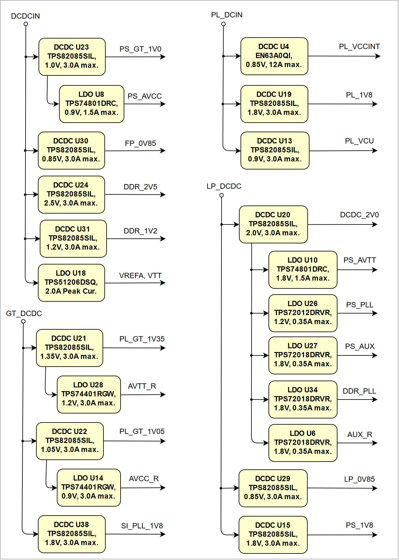 Image Added Image Added
|
|
See also Xilinx datasheet DS925 for additional information. User should also check related base board documentation when intending base board design for TE0807 module.
...
The on-board voltages of the TE0808 TE0807 SoM will be powered-up in order of a determined sequence by activating the above-mentioned power rails and the Enable-Signals of the DC-DC converters. The on-board voltages will be powered up at three steps.
...
| Scroll Title |
|---|
| anchor | Figure_4 |
|---|
| title | Figure 4: TE0807-01 Power-on Sequence Diagram03 Power-on Sequence Diagram |
|---|
|
| Scroll Ignore |
|---|
| draw.io Diagram |
|---|
| border | false |
|---|
| viewerToolbar | true |
|---|
| |
|---|
| fitWindow | false |
|---|
| diagramDisplayName | |
|---|
| lbox | true |
|---|
| revision | 2 |
|---|
| diagramName | TE0807 Power-On Sequence Diagram |
|---|
| simpleViewer | false |
|---|
| width | |
|---|
| links | auto |
|---|
| tbstyle | hidden |
|---|
| diagramWidth | 648 |
|---|
|
| scroll-ignore |
| Scroll Only |
|---|
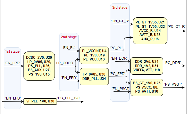 Image Added Image Added
|
|
Operation Conditions of the DC-DC Converter Control Signals
The control signals have to be asserted on the B2B connector J2, whereby some of the Power-Good signals need external pull-up resistors.
| Enable-Signal | B2B Connector Pin | Max. Voltage | Note |
| Power-Good-Signal | B2B Connector Pin | Pull-up Resistor | Note |
|---|
| EN_LPD | J2-108 | 6V | TPS82085SIL data sheet |
| LP_GOOD | J2-106 | 4K7, pulled up to LP_DCDC | - |
|---|
| EN_FPD | J2-102 | DCDCIN | NC7S08P5X data sheet |
| PG_FPD | J2-110 | 4K7, pulled up to DCDCIN | - |
|---|
| EN_PL | J2-101 | PL_DCIN | left floating for logic high
(drive to GND for logic low) |
| PG_PL | J2-104 |
|---|
External pull-up needed (max. voltage GT_DCDC),
max. sink current 1 mA | TPS82085SIL /
NC7S08P5X data sheet | | 4K7, pulled up to PL_DCIN | - |
| EN_DDR | J2-112 | DCDCIN | NC7S08P5X data sheet |
| PG_DDR | J2-114 | 4K7, pulled up to DCDCIN |
|---|
- | EN_PSGT | J2-84 | DCDCIN | NC7S08P5X data sheet | PG_PSGT | J2-82 | External pull-up needed (max. 5.5V),
max. sink current 1 mA | TPS74801 data sheet | EN_GT_R | J2-95 | GT_DCDC | - |
| EN_PSGT | J2-84 | DCDCIN | NC7S08P5X data sheet |
| PG_ |
|---|
GT_R91| 82 | External pull-up needed (max. 5.5V),
max. sink current 1 mA |
TPS74401 | TPS74801 data sheet |
| EN_GT_ |
L79| 95 | GT_DCDC | NC7S08P5X data sheet |
| PG_GT_ |
|---|
L97| 91 | External pull-up needed (max. 5.5V),
max. sink current 1 mA |
TPS74801 | TPS74401 data sheet |
| EN_PLL_PWR | J2-77 | 6V | TPS82085SIL data sheet |
| PG_PLL_1V8 | J2-80 | External pull-up needed (max. 5.5V),
max. sink current 1 mA | TPS82085SIL data sheet |
|---|
Table 1618: Recommended operation conditions of DC-DC converter control signals.
...
| Scroll Title |
|---|
| anchor | Figure_5 |
|---|
| title | Figure 5: TE0784TE0807-01 02 Voltage Monitor Circuit |
|---|
|
| Scroll Ignore |
|---|
| draw.io Diagram |
|---|
| border | false |
|---|
| viewerToolbar | true |
|---|
| |
|---|
| fitWindow | false |
|---|
| diagramDisplayName | |
|---|
| lbox | true |
|---|
| revision | 1 |
|---|
| diagramName | TE0807 Voltage Monitor Circuit |
|---|
| simpleViewer | false |
|---|
| width | |
|---|
| links | auto |
|---|
| tbstyle | hidden |
|---|
| diagramWidth | 641 |
|---|
|
|
| Scroll Only |
|---|
 Image Added Image Added
|
|
Power Rails
Power Rail Name | B2B J1 Pins | B2B J2 Pins | B2B J3 Pins | B2B J4 Pins | Directions | Note |
|---|
| PL_DCIN | 151, 153, 155, 157, 159 | - | - | - | Input | - |
| DCDCIN | - | 154, 156, 158, 160,
153, 155, 157, 159 | - | - | Input | - |
| LP_DCDC | - | 138, 140, 142, 144 | - | - | Input | - |
| PS_BATT | - | 125 | - | - | Input | - |
| GT_DCDC | - | - | 157, 158, 159, 160 | - | Input | - |
| PLL_3V3 | - | - | 152 | - | Input | U5 (programmable PLL)
3.3V nominal input |
| SI_PLL_1V8 | - | - | 151 | - | Output | Internal voltage level
1.8V nominal output |
| PS_1V8 | - | 99 | 147, 148 | - | Output | Internal voltage level
1.8V nominal output |
| PL_1V8 | 91, 121 | - | - | - | Output | Internal voltage level
1.8V nominal output |
| DDR_1V2 | - | 135 | - | - | Output | Internal voltage level
1.2V nominal output |
| VCCO47 | - | - | 43, 44 | - | Input | - |
| VCCO48 | - | - | 15, 16 | - | Input | - |
| VCCO64 | - | - | - | 58, 106 | Input | - |
| VCCO65 | - | - | - | 69, 105 | Input | - |
| VCCO66 | 90, 120 | - | - | - | Input | - |
Table 19Table 16: TE0807-01 03 power rails
Bank Voltages
/ B2B Connector Pins | Voltage | Reference Input Voltage | Voltage Range |
|---|
| 47 | HD | VCCO47 |
, pins J3-43, J3-44max, pins J3-15, J3-16max, J4-58, J4-106max, J4-69, J4-105max, J1-90, J1-120max| 1.2V to 1.8V |
| 500 | MIO | PS_1V8 | 1.8V | - | - |
| 501 | MIO | PS_1V8 | 1.8V | - | - |
| 502 | MIO | PS_1V8 | 1.8V | - | - |
| 503 | CONFIG | PS_1V8 | 1.8V | - | - |
Table 1720: TE0807-01 03 I/O bank voltages
See Xilinx Zynq UltraScale+ datasheet DS925 for the voltage ranges allowed.
...
Variants Currently In Production
Technical Specifications
Absolute Maximum Ratings
Parameter | Min | Max | Unit | Notes / Reference Document |
|---|
| PL_DCIN | -0.3 |
7| 4 | V | TPS82085SIL / EN63A0QI data sheet/ Limit is LP_DCDC over EN/PG |
| DCDCIN | -0.3 |
7 / TPS51206 data sheet| / TPS51206 data sheet/ Limit is LP_DCDC over EN/PG |
| LP_DCDC | -0.3 | 4 | V | TPS3106K33DBVR data sheet |
| GT_DCDC | -0.3 |
7| 4 | V | TPS82085SIL data sheet/ Limit is LP_DCDC over EN/PG |
| PS_BATT | -0.5 | 2 | V | Xilinx DS925 data sheet |
| PLL_3V3 | -0.5 | 3.8 | V | Si5345/44/42 data sheet |
| VCCO for HD I/O banks | -0.5 | 3.4 | V | Xilinx DS925 data sheet |
| VCCO for HP I/O banks |
-0.5 | 2 | VXilinx DS925 data sheet | VREF | | -0.5 | 2 | V | Xilinx DS925 data sheet |
| I/O input voltage for HD I/O banks | -0.55 | VCCO + 0.55 | V | Xilinx DS925 data sheet |
| I/O input voltage for HP I/O banks | -0.55 | VCCO + 0.55 | V | Xilinx DS925 data sheet |
| PS I/O input voltage (MIO pins) | -0.5 | VCCO_PSIO + 0.55 | V | Xilinx DS925 data sheet,
VCCO_PSIO 1.8V nominally |
| PS GTR reference clocks absolute input voltage | -0.5 | 1.1 | V | Xilinx document DS925 |
| PS GTR absolute input voltage | -0.5 | 1.1 | V | Xilinx document DS925 |
| MGT clock absolute input voltage | -0.5 | 1.3 | V | Xilinx document DS925 |
MGT Receiver (RXP/RXN) and transmitter
(TXP/TXN) absolute input voltage | -0.5 | 1.2 | V | Xilinx DS925 data sheet |
Voltage on input pins of
NC7S08P5X 2-Input AND Gate | -0.5 | VCC + 0.5 | V | NC7S08P5X data sheet,
see schematic for VCC |
Voltage on input pins (nMR) of
TPS3106K33DBVR Voltage Monitor, U41 | -0.3 | VDD + 0.3 | V | TPS3106 data sheet,
VDD = LP_DCDC |
"Enable"-signals on TPS82085SIL
(EN_PLL_PWR, EN_LPD) | -0.3 | 7 | V | TPS82085SIL data sheet |
Storage temperature (ambient) | -40 | 100 | °C | ROHM Semiconductor SML-P11 Series data sheet |
Table 1821: Module absolute maximum ratings
...
Recommended Operating Conditions
| Parameter | Min | Max | Unit | Notes / Reference Document |
|---|
| PL_DCIN |
25| 3 | 3.6 | V | EN63A0QI / TPS82085SIL data sheet/ Limit is LP_DCDC over EN/PG |
| DCDCIN | 3. |
1| 3 | 3.6 | V | TPS82085SIL / TPS51206PSQ data sheet/ Limit is LP_DCDC over EN/PG |
| LP_DCDC |
25| 3 | 3.6 | V | TPS82085SIL / TPS3106 data sheet |
| GT_DCDC |
25| 3 | 3.6 | V | TPS82085SIL data sheet/ Limit is LP_DCDC over EN/PG |
| PS_BATT | 1.2 | 1.5 | V | Xilinx DS925 data sheet |
| PLL_3V3 | 3. |
14| 3 | 3.47 | V | Si5345/44/42 data sheet
3.3V typical |
| VCCO for HD I/O banks | 1.14 | 3.4 | V | Xilinx DS925 data sheet |
| VCCO for HP I/O banks | 0.95 | 1.9 | V | Xilinx DS925 data sheet |
| I/O input voltage for HD I/O banks. | -0.2 | VCCO + 0.2 | V | Xilinx DS925 data sheet |
| I/O input voltage for HP I/O banks | -0.2 | VCCO + 0.2 | V | Xilinx DS925 data sheet |
| PS I/O input voltage (MIO pins) | -0.2 | VCCO_PSIO + 0.2 | V | Xilinx DS925 data sheet,
VCCO_PSIO 1.8V nominally |
| PL bank reference voltage VREF pin | -0.5 | 2 | V | Xilinx DS925 data sheet |
Voltage on input pins of
NC7S08P5X 2-Input AND Gate | 0 | VCC | V | NC7S08P5X data sheet,
see schematic for VCC |
Voltage on input pin 'MR' of
TPS3106K33DBVR Voltage Monitor, U41 | 0 | VDD | V | TPS3106 data sheet,
VDD = LP_DCDC |
Table 1922: Recommended operating conditions
...
Module size: 52 mm × 76 mm. Please download the assembly diagram for exact numbers
Mating height with standard connectors: 4mm5mm
PCB thickness: 1.6mm
Highest part on PCB: approx. 3mm. Please download the step model for exact numbers
...
| Scroll Title |
|---|
| anchor | Figure_6 |
|---|
| title | Figure 6: Module physical dimensions drawing |
|---|
|
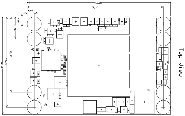 Image Added Image Added 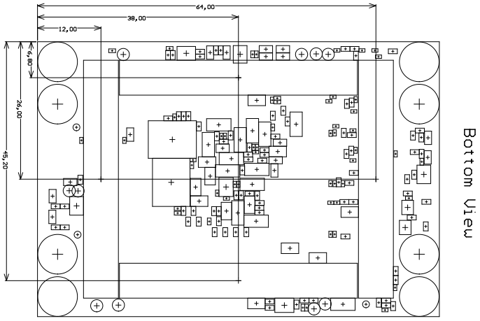 Image Added Image Added
|
Revision History
Hardware Revision History
Notes | PCN Link | Documentation Link01Table 2023: Hardware revision history table
...
| Scroll Title |
|---|
| anchor | Figure_7 |
|---|
| title | Figure 7: Module hardware revision number |
|---|
|
| draw.io Diagram |
|---|
| border | true |
|---|
| |
|---|
| diagramName | TE0807-03_HRN |
|---|
| simpleViewer | false |
|---|
| width | |
|---|
| links | auto |
|---|
| tbstyle | top |
|---|
| lbox | true |
|---|
| diagramWidth | 180 |
|---|
| revision | 1 |
|---|
|
|
Document Change History
| HTML |
|---|
<!--
Generate new entry:
1.add new row below first
2.Copy "Page Information Macro(date)" Macro-Preview, Metadata Version number, Author Name and description to the empty row. Important Revision number must be the same as the Wiki document revision number must be the same as the Wiki document revision number
3.Update Metadata = "Page Information Macro (current-version)" Preview+1 and add Author and change description.
--> |
...
Date
...
Revision
...
Contributors
...
Description
...
| Page info |
|---|
| infoType | Current version |
|---|
| dateFormat | yyyy-MM-dd |
|---|
| type | Flat |
|---|
|
...
| Page info |
|---|
| infoType | Modified by |
|---|
| dateFormat | yyyy-MM-dd |
|---|
| type | Flat |
|---|
|
...
3.Update Metadata = "Page Information Macro (current-version)" Preview+1 and add Author and change description.
--> |
Date | Revision | Contributors | Description |
|---|
| Page info |
|---|
| modified-date |
|---|
| modified-date |
|---|
| dateFormat | yyyy-MM-dd |
|---|
|
| | Page info |
|---|
| infoType | Current version |
|---|
| dateFormat | yyyy-MM-dd |
|---|
| prefix | v. |
|---|
| type | Flat |
|---|
|
| | Page info |
|---|
| infoType | Modified by |
|---|
| dateFormat | yyyy-MM-dd |
|---|
| type | Flat |
|---|
|
| - Correction on MGT Lanes (column "FPGA Pin" of bank 227 and 505 was incorrect)
|
| | | - Correction on Power section
|
| 2021-06-10 | v.27 | John Hartfiel | - correction number IOs in BD
|
| 2021-05-17 | v.26 | John Hartfiel | - typo correction in DDR section
|
| 2021-05-03 | v.25 | Martin Rohrmüller | |
| v.24 | Antti Lukats | - Corrected B2B include macro
|
| v.22 | John Hartfiel | - typo correction SI5345 I2C address
- typo B2B Pin of CLK signals
|
| v.20 | Ali Naseri | |
Table 24Table 21: Document change history
Disclaimer
...