Page History
...
| Excerpt |
|---|
|
Revision History
| HTML |
|---|
<!-- - Add changes from design - Export PDF to download, if vivado revision is changed! --> |
...
| Date | Vivado | Project Built | Authors | Description |
|---|---|---|---|---|
| 2018-01-24 | 2017.4 | TE0820-test_board-vivado_2017.4-build_05_20180124085247.zip TE0820-test_board_noprebuilt-vivado_2017.4-build_05_20180124085303.zip | John AHrtfiel |
|
| 2017-11-21 | 2017.2 | TE0820-test_board-vivado_2017.2-build_05_20171121160552.zip TE0820-test_board_noprebuilt-vivado_2017.2-build_05_20171121160606.zip | John Hartfiel |
|
| 2017-11-20 | 2017.2 | TE0820-test_board-vivado_2017.2-build_05_20171120162931.zip TE0820-test_board_noprebuilt-vivado_2017.2-build_05_20171120162851.zip | John Hartfiel |
|
| 2017-10-19 | 2017.2 | TE0820-test_board-vivado_2017.2-build_05_20171019104824.zip TE0820-test_board_noprebuilt-vivado_2017.2-build_05_20171019104837.zip | John Hartfiel |
|
...
| Issues | Description | Workaround | To be fixed version | ||||
|---|---|---|---|---|---|---|---|
| USB2.0 | works only with USB3.0 enabled in Vivado Design | enable USB3.0 | --- | ||||
| Boot Mode | for 4x5 carrier compatibility, currently 2 different CPLD Firmware files are available. | Reprogram CPLD (TE0820 CPLD Firmware) | 2017.4 with special FSBL | ||||
| --- | --- | --- | --- | PHY LED | PHY LED is on X1 instead X0 as described | -- | 2017.4
Requirements
Software
| HTML |
|---|
<!-- Add needed external Software --> |
...
| Software | Version | Note |
|---|---|---|
| Vivado | 2017.24 | needed |
| SDK | 2017.24 | needed |
| PetaLinux | 2017.24 | needed |
| SI5338 Clock Builder | --- | optional |
...
Reference Design is available on:
- TE0820 "Test Board" Reference Design Download Area
Design Flow
| HTML |
|---|
<!-- Basic Design Steps Add/ Remove project specific --> |
...
- _create_win_setup.cmd/_create_linux_setup.sh and follow instructions on shell:
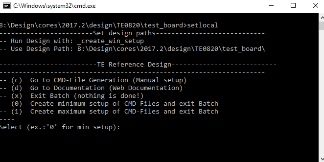
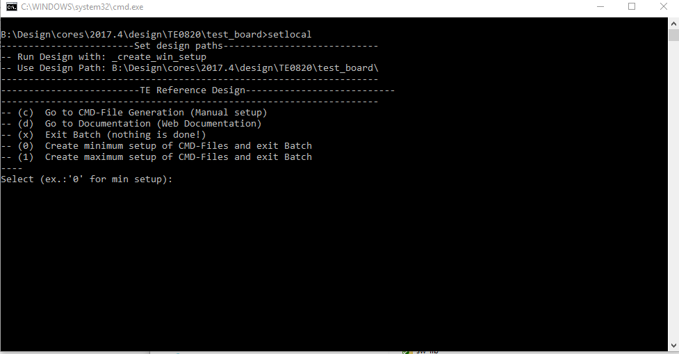
- Press 0 and enter for minimum setup
- (optional Win OS) Generate Virtual Drive or use short directory for the reference design (for example x:\<design name>)
- Create Project
- Select correct device and Xilinx install path on "design_basic_settings.cmd" and create Vivado project with "vivado_create_project_guimode.cmd"
Note: Select correct one, see TE Board Part Files
- Select correct device and Xilinx install path on "design_basic_settings.cmd" and create Vivado project with "vivado_create_project_guimode.cmd"
- Create HDF and export to prebuilt folder
- Run on Vivado TCL: TE::hw_build_design -export_prebuilt
Note: Script generate design and export files into \prebuilt\hardware\<short dir>. Use GUI is the same, except file export to prebuilt folder
- Run on Vivado TCL: TE::hw_build_design -export_prebuilt
- Create Linux (bl31.elf, uboot.elf and image.ub) with exported HDF
- HDF is exported to "prebuilt\hardware\<short name>"
Note: HW Export from Vivado GUI create another path as default workspace. - Create Linux images on VM, see PetaLinux KICKstart
- Use TE Template from /os/petalinux
Note: run init_config.sh before you start petalinux config. This will set correct temporary path variable.
- Use TE Template from /os/petalinux
- HDF is exported to "prebuilt\hardware\<short name>"
- Add Linux files (bl31.elf, uboot.elf and image.ub) to prebuilt folder
- "prebuilt\os\petalinux\default" or "prebuilt\os\petalinux\<short name>"
Notes: Scripts select "prebuilt\os\petalinux\<short name>", if exist, otherwise "prebuilt\os\petalinux\default"
- "prebuilt\os\petalinux\default" or "prebuilt\os\petalinux\<short name>"
- Generate Programming Files with HSI/SDK
- Run on Vivado TCL: TE::sw_run_hsi
Note: Scripts generate applications and bootable files, which are defined in "sw_lib\apps_list.csv" - (alternative) Start SDK with Vivado GUI or start with TE Scripts on Vivado TCL: TE::sw_run_sdk
Note: See SDK Projects
- Run on Vivado TCL: TE::sw_run_hsi
...
Note: Depending on CPLD Firmware and Boot Mode settings, QSPI boot with Linux image on SD or complete SD Boot is possible.
QSPI
...
Optional for Boot.bin on QSPI Flash and image.ub on SD.
- Connect JTAG and power on carrier with module
- Open Vivado Project with "vivado_open_existing_project_guimode.cmd"
...
- or if not created, create with "vivado_
...
- create_project_guimode.cmd"
...
- Type on Vivado TCL Console:
...
- TE::pr_program_flash_
...
- binfile -swapp
...
- u-boot
...
Note:
...
- To program with SDK/Vivado GUI, use special FSBL (zynqmp_fsbl_flash) on setup
- Copy image.ub on SD-Card
- For correct prebuilt file location, see <design_name>/prebuilt/readme_file_location.txt
- Insert SD-Card
SD
Use Use this description for CPLD Firmware with QSPI SD Boot selectable.
- Set Boot Mode to JTAG (See Carrier and TE0820 CPLD description)
- Connect JTAG
- Power ON PCB
- Program Flash
- Open Vivadi HW-Manager (use Auto Connect)
- Right Click on FPGA Device (xczu...) and "Add Configuration Memory Device"
- Select "mt25qu256-qspi-x8-dual_parallel"
- On "Program Configuration Memory Device":
- Set Configuration file: "prebuilt\boot_images\<short name>\u-boot\BOOT.bin"
- Set Zynq FSBL: "prebuilt\software\<short name>\zynqmp_fsbl.elf"
- Press OK
- Note: Other possible ways, see Vivado/SDK/SDSoC-Xilinx Software Programming and Debugging
Do not use Trenz Script for Programming at the moment. Dual Parallel Flash Scripts support is not implemented.
- Copy image.ub on SD-Card.
- For correct prebuilt file location, see <design_name>/prebuilt/readme_file_location.txt
- Power OFF PCB
- Set Boot Mode to QSPI
- Depends on Carrier, see carrier TRM.
SD
Use this description for CPLD Firmware with SD Boot selectable.
- Copy image.ub and Boot.bin on SD-Card.
- For correct prebuilt file location, see <design_name>/prebuilt/readme_file_location.txt
- Set Boot Mode to SD-Boot.
- Depends on Carrier, see carrier TRM.
- Insert SD-Card in SD-Slot.
JTAG
Not used on this Example.
Usage
- Prepare HW like described on section Programming
- Connect UART USB (most cases same as JTAG)
- Select SD Card or QSPI as Boot Mode (Depends on used programming variant)
Note: See TRM of the Carrier, which is used. - Power On PCB
Note: 1. ZynqMP Boot ROM loadsPMU Firmware and FSBL from SD into OCM, 2. FSBL loads ATF(bl31.elf)and U-boot from SD into DDR, 3. U-boot load Linux from SD into DDR
Linux
- Open Serial Console (e.g. putty)
- Speed: 115200
- COM Port: Win OS, see device manager, Linux OS see dmesg |grep tty (UART is *USB1)
- Linux Console:
Note: Wait until Linux boot finished For Linux Login use:- User Name: root
- Password: root
- You can use Linux shell now.
- I2C 0 Bus type: i2cdetect -y -r 0
- RTC check: dmesg | grep rtc
- ETH0 works with udhcpc
- USB type "lsusb" or connect USB2.0 device
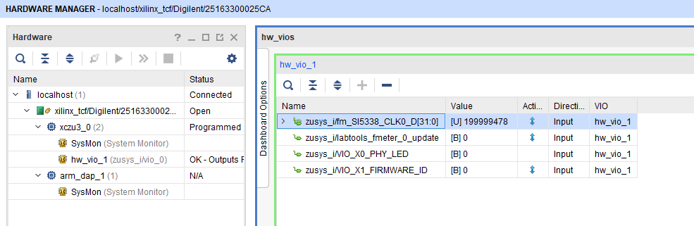
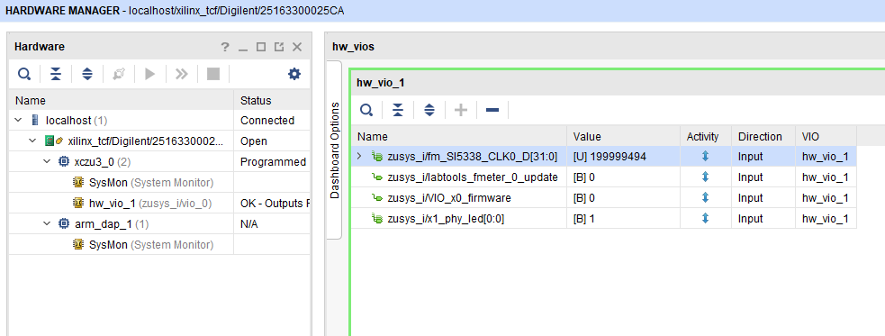
Vivado HW Manager
SI5338_CLK0 Counter:
- Open Vivado HW-Manager and add VIO signal to dashboard (*.ltx located on prebuilt folder).
- Set radix from VIO signals to unsigned integer.
Note: Frequency Counter is inaccurate and displayed unit is Hz
- Set radix from VIO signals to unsigned integer.
SI5338 CLK is configured to 200MHz by default.
PHY LEDS
- See: TE0820 CPLD#X0/X1Pin
CPLD Firmware:
- See: TE0820 CPLD#X0/X1Pin
System Design - Vivado
| HTML |
|---|
<!--
Description of Block Design, Constrains...
BD Pictures from Export...
--> |
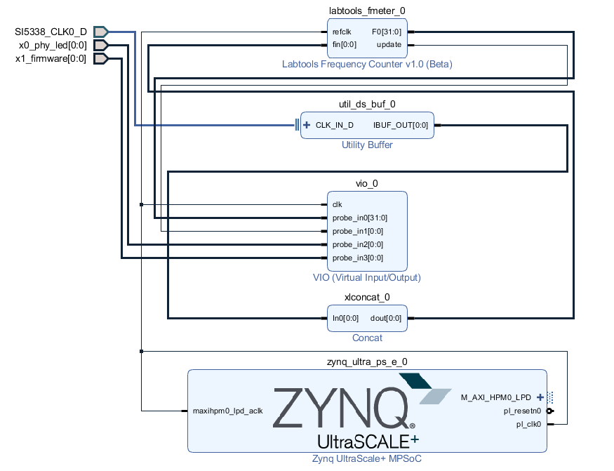
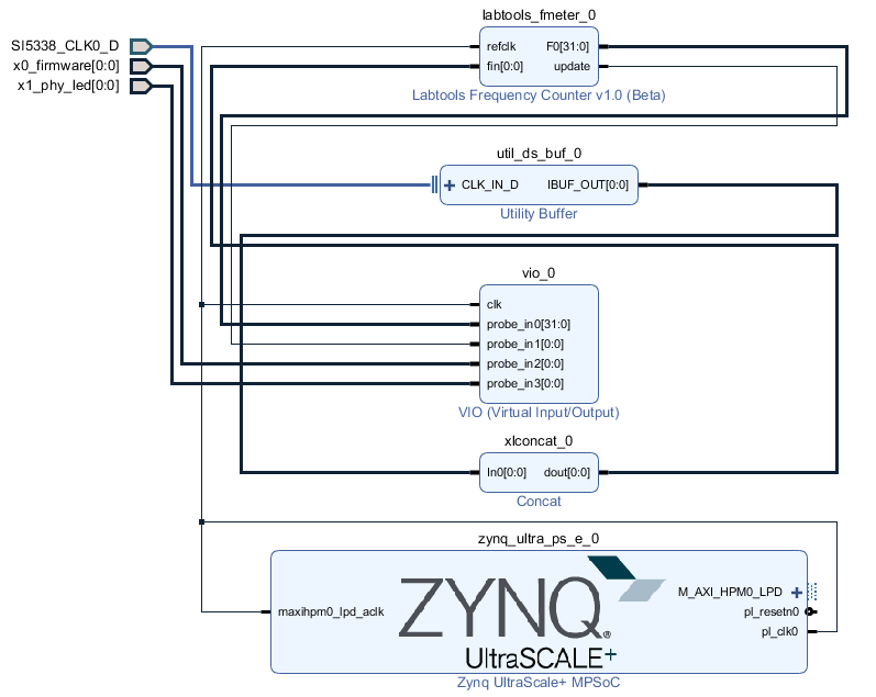
Block Design
PS Interfaces
Activated interfaces:
...
- Copy image.ub and Boot.bin on SD-Card.
- For correct prebuilt file location, see <design_name>/prebuilt/readme_file_location.txt
- Insert SD-Card in SD-Slot.
JTAG
Not used on this Example.
Usage
- Prepare HW like described on section Programming
- Connect UART USB (most cases same as JTAG)
- Select SD Card or QSPI as Boot Mode (Depends on used programming variant)
Note: See TRM of the Carrier, which is used. - Power On PCB
Note: 1. ZynqMP Boot ROM loadsPMU Firmware and FSBL from SD/QSPI Flash into OCM, 2. FSBL loads ATF(bl31.elf)and U-boot from SD into DDR, 3. U-boot load Linux from SD into DDR
Linux
- Open Serial Console (e.g. putty)
- Speed: 115200
- COM Port: Win OS, see device manager, Linux OS see dmesg |grep tty (UART is *USB1)
- Linux Console:
Note: Wait until Linux boot finished For Linux Login use:- User Name: root
- Password: root
- You can use Linux shell now.
- I2C 0 Bus type: i2cdetect -y -r 0
- RTC check: dmesg | grep rtc
- ETH0 works with udhcpc
- USB type "lsusb" or connect USB2.0 device
Vivado HW Manager
SI5338_CLK0 Counter:
- Open Vivado HW-Manager and add VIO signal to dashboard (*.ltx located on prebuilt folder).
- Set radix from VIO signals to unsigned integer.
Note: Frequency Counter is inaccurate and displayed unit is Hz
- Set radix from VIO signals to unsigned integer.
SI5338 CLK is configured to 200MHz by default.
PHY LEDS
- See: TE0820 CPLD#X0/X1Pin
CPLD Firmware:
- See: TE0820 CPLD#X0/X1Pin
System Design - Vivado
| HTML |
|---|
<!--
Description of Block Design, Constrains...
BD Pictures from Export...
--> |
Block Design
PS Interfaces
Activated interfaces:
| Type | Note |
|---|---|
| DDR | |
| QSPI | MIO |
| SD0 | MIO |
| SD1 | MIO |
| I2C0 | MIO |
| UART0 | MIO |
| GPIO0 | MIO |
| SWDT0..1 | |
| TTC0..3 | |
| GEM3 | MIO |
| USB0 | MIO |
Constrains
Basic module constrains
| Code Block | ||||
|---|---|---|---|---|
| ||||
set_property BITSTREAM.GENERAL.COMPRESS TRUE [current_design]
set_property BITSTREAM.CONFIG.UNUSEDPIN PULLNONE [current_design |
Design specific constrain
| Code Block | ||||
|---|---|---|---|---|
| ||||
set_property PACKAGE_PIN K9 [get_ports {SI5338_ |
Constrains
Basic module constrains
| Code Block | ||||
|---|---|---|---|---|
| ||||
set_property BITSTREAM.GENERAL.COMPRESS TRUE [current_design]
set_property BITSTREAM.CONFIG.UNUSEDPIN PULLNONE [current_design |
Design specific constrain
| Code Block | ||||
|---|---|---|---|---|
| ||||
set_property PACKAGE_PIN K9 [get_ports {SI5338_CLK0_D_clk_p[0]}] set_property IOSTANDARD LVDS [get_ports {SI5338_CLK0_D_clk_p[0]}] set_property DIFF_TERM TRUE [get_ports {SI5338_CLK0_D_clk_p[0]}] set_property PACKAGE_PIN H1 [get_ports {x0_phy_ledfirmware[0]}] set_property IOSTANDARD LVCMOS18 [get_ports {x0_phy_ledfirmware[0]}] set_property PACKAGE_PIN J1 [get_ports {x1_phy_firmwareled[0]}] set_property IOSTANDARD LVCMOS18 [get_ports {x1_phy_firmwareled[0]}] |
Software Design - SDK/HSI
...
For SDK project creation, follow instructions from:
Application
...
zynqmp_fsbl
TE modified 2017.2 4 FSBL
Changes:
- Si5338 Configuration, ETH+OTG Reset over GPIO see xfsbl_board.c and , xfsbl_board.h
- Add register_map.h, si5338.c, si5338.h
PMU
zynqmp_fsbl_flash
TE modified 2017.4 FSBL
Changes:
- Set FSBL Boot Mode to JTAG
- Disable Memory initialisation
zynqmp_pmufw
Xilinx default Xilinx default PMU firmware.
Hello
...
TE0820
Hello TE0820 is a Xilinx default Hello world example. Note: Hello World output appears only on time on power up. World example as endless loop instead of one console output.
U-Boot
U-Boot.elf is generated with PetaLinux. SDK/HSI is used to generate Boot.bin.
Software Design - PetaLinux
| HTML |
|---|
<!--
optional chapter
Add "No changes." or "Activate: List"
--> |
For PetaLinux installation and project creation, follow instructions from:
Config
No changes.
U-Boot
- Change platform-top.h
| Code Block | ||
|---|---|---|
| ||
#include <configs/platform-auto.h>

/* Bugfix to select SD1 instead of eMMC(SD0) */
#define CONFIG_EXTRA_ENV_SETTINGS \
    SERIAL_MULTI \
    CONSOLE_ARG \
    PSSERIAL0 \
    "nc=setenv stdout nc;setenv stdin nc;\0" \
    "ethaddr=00:0a:35:00:22:01\0" \
    "importbootenv=echo \"Importing environment from SD ...\"; " \
        "env import -t ${loadbootenv_addr} $filesize\0" \
    "loadbootenv=load mmc $sdbootdev:$partid ${loadbootenv_addr} ${bootenv}\0" \
    "sd_uEnvtxt_existence_test=test -e mmc $sdbootdev:$partid /uEnv.txt\0" \
    "uenvboot=" \
    "if run sd_uEnvtxt_existence_test; then" \
        "run loadbootenv" \
        "echo Loaded environment from ${bootenv};" \
        "run importbootenv; \0" \
    "sdboot=echo boot Petalinux; run uenvboot ; mmcinfo && fatload mmc 1 ${netstart} ${kernel_img} && bootm \0" \
    "autoload=no\0" \
    "clobstart=0x10000000\0" \
    "netstart=0x10000000\0" \
    "dtbnetstart=0x11800000\0" \
    "loadaddr=0x10000000\0" \
    "boot_img=BOOT.BIN\0" \
    "load_boot=tftpboot ${clobstart} ${boot_img}\0" \
    "update_boot=setenv img boot; setenv psize ${bootsize}; setenv installcmd \"install_boot\"; run load_boot ${installcmd}; setenv img; setenv psize; setenv installcmd\0" \
    "install_boot=mmcinfo && fatwrite mmc 1 ${clobstart} ${boot_img} ${filesize}\0" \
    "bootenvsize=0x40000\0" \
    "bootenvstart=0x100000\0" \
    "eraseenv=sf probe 0 && sf erase ${bootenvstart} ${bootenvsize}\0" \
    "jffs2_img=rootfs.jffs2\0" \
    "load_jffs2=tftpboot ${clobstart} ${jffs2_img}\0" \
    "update_jffs2=setenv img jffs2; setenv psize ${jffs2size}; setenv installcmd \"install_jffs2\"; run load_jffs2 test_img; setenv img; setenv psize; setenv installcmd\0" \
    "sd_update_jffs2=echo Updating jffs2 from SD; mmcinfo && fatload mmc 1:1 ${clobstart} ${jffs2_img} && run install_jffs2\0" \
    "install_jffs2=sf probe 0 && sf erase ${jffs2start} ${jffs2size} && " \
        "sf write ${clobstart} ${jffs2start} ${filesize}\0" \
    "kernel_img=image.ub\0" \
    "load_kernel=tftpboot ${clobstart} ${kernel_img}\0" \
    "update_kernel=setenv img kernel; setenv psize ${kernelsize}; setenv installcmd \"install_kernel\"; run load_kernel ${installcmd}; setenv img; setenv psize; setenv installcmd\0" \
    "install_kernel=mmcinfo && fatwrite mmc 1 ${clobstart} ${kernel_img} ${filesize}\0" \
    "cp_kernel2ram=mmcinfo && fatload mmc 1 ${netstart} ${kernel_img}\0" \
    "dtb_img=system.dtb\0" \
    "load_dtb=tftpboot ${clobstart} ${dtb_img}\0" \
    "update_dtb=setenv img dtb; setenv psize ${dtbsize}; setenv installcmd \"install_dtb\"; run load_dtb test_img; setenv img; setenv psize; setenv installcmd\0" \
    "sd_update_dtb=echo Updating dtb from SD; mmcinfo && fatload mmc 1:1 ${clobstart} ${dtb_img} && run install_dtb\0" \
    "fault=echo ${img} image size is greater than allocated place - partition ${img} is NOT UPDATED\0" \
    "test_crc=if imi ${clobstart}; then run test_img; else echo ${img} Bad CRC - ${img} is NOT UPDATED; fi\0" \
    "test_img=setenv var \"if test ${filesize} -gt ${psize}\\; then run fault\\; else run ${installcmd}\\; fi\"; run var; setenv var\0" \
    "netboot=tftpboot ${netstart} ${kernel_img} && bootm\0" \
    "default_bootcmd=run cp_kernel2ram && bootm ${netstart}\0" \
"" |
Device Tree
--
optional chapter
Add "No changes." or "Activate: List"
--> |
For PetaLinux installation and project creation, follow instructions from:
Config
No changes.
U-Boot
- Change platform-top.h
| Code Block | ||
|---|---|---|
| ||
#include <configs/platform-auto.h>
#define CONFIG_SYS_BOOTM_LEN 0xF000000

#define DFU_ALT_INFO_RAM \
                "dfu_ram_info=" \
        "setenv dfu_alt_info " \
        "image.ub ram $netstart 0x1e00000\0" \
        "dfu_ram=run dfu_ram_info && dfu 0 ram 0\0" \
        "thor_ram=run dfu_ram_info && thordown 0 ram 0\0"

#define DFU_ALT_INFO  \
                DFU_ALT_INFO_RAM

/*Required for uartless designs */
#ifndef CONFIG_BAUDRATE
#define CONFIG_BAUDRATE 115200
#ifdef CONFIG_DEBUG_UART
#undef CONFIG_DEBUG_UART
#endif
#endif

/*select sd instead of mmc for autoboot */


#define CONFIG_BOOTCOMMAND    "run uenvboot;  mmcinfo && fatload mmc 1 ${netstart} ${kernel_img};bootm ${netstart}"
|
Device Tree
| Code Block | ||
|---|---|---|
| ||
/include/ "system-conf.dtsi"
/ {
};


/* SDIO */

&sdhci1 {
   disable-wp;
   no-1-8-v;
};

/* ETH PHY */
&gem3 {

    status = "okay";
  ethernet_phy0: ethernet-phy@0 {
        compatible = "marvell,88e1510";
        device_type = "ethernet-phy";
            reg = <1>;
    };
};
/* USB 2.0 */

&dwc3_0 {
    status = "okay";
    dr_mode = "host";
    maximum-speed = "high-speed";
    /delete-property/phy-names;
    /delete-property/phys;
    /delete-property/snps,usb3_lpm_capable;
}; | ||
| Code Block | ||
| ||
/include/ "system-conf.dtsi"
/ {
};


/* SDIO */

&sdhci1 {
   disable-wp;
   no-1-8-v;
};

/* ETH PHY */
&gem3 {

    status = "okay";
  ethernet_phy0: ethernet-phy@0 {
        compatible = "marvell,88e1510";
        device_type = "ethernet-phy";
            reg = <1>;
    };
};


/* QSPI PHY */
&qspi {
    #address-cells = <1>;
    #size-cells = <0>;
    status = "okay";
    flash0: flash@0 {
        compatible = "n25q256a";
        reg = <0x0>;
        #address-cells = <1>;
        #size-cells = <1>;
    };
};

/* DMA not used: Reduce error messages on linux.*/

&lpd_dma_chan1 {
    status = "disabled";
};
&lpd_dma_chan2 {
    status = "disabled";
};
&lpd_dma_chan3 {
    status = "disabled";
};
&lpd_dma_chan4 {
    status = "disabled";
};
&lpd_dma_chan5 {
    status = "disabled";
};
&lpd_dma_chan6 {
    status = "disabled";
};
&lpd_dma_chan7 {
    status = "disabled";
};
&lpd_dma_chan8 {
    status = "disabled";
};
|
...
| Date | Document Revision | Authors | Description | ||||||||||||||||||||||
|---|---|---|---|---|---|---|---|---|---|---|---|---|---|---|---|---|---|---|---|---|---|---|---|---|---|
|
|
|
| ||||||||||||||||||||||
| 2018-01-10 | v.24 | John Hartfiel |
| ||||||||||||||||||||||
| 2017-12-20 | v.23 | John Hartfiel |
| ||||||||||||||||||||||
| 2017-11-21 | v.19 | John Hartfiel |
| ||||||||||||||||||||||
| 2017-11-20 | v.18 | John Hartfiel |
| ||||||||||||||||||||||
| 2017-11-13 | v.16 | John Hartfiel |
| ||||||||||||||||||||||
| 2017-11-06 | v.15 | John Hartfiel |
| ||||||||||||||||||||||
| 2017-10-23 | v.13 | John Hartfiel |
| ||||||||||||||||||||||
| 2017-10-19 | v.9 | John Hartfiel |
| ||||||||||||||||||||||
| 2017-09-11 | v.1 |
| Initial release | ||||||||||||||||||||||
| All |
|
...
Overview
Content Tools