Page History
...
System controller chip is Intel MAX10 10M08SAU169C8G Chip with board control firmware.
FTDIs
FT2232H
FT601Q-B-T
Quad-SPI Flash Memory
Board has two N25Q512A11G1240E connected in a dual parallel mode.
EEPROMs
I2C
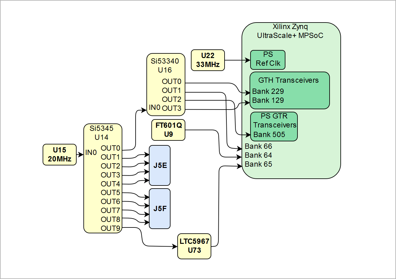
Programmable Clock Generators
| Scroll Title | ||||||||||||||||||||||||||||||||
|---|---|---|---|---|---|---|---|---|---|---|---|---|---|---|---|---|---|---|---|---|---|---|---|---|---|---|---|---|---|---|---|---|
| ||||||||||||||||||||||||||||||||
|
I2C
The onboard I2C bus The onboard I2C bus is connected to MIO 20...21 pins. Devices on the bus shown in the table below.
| I2C address | Chip | Description |
|---|---|---|
| 0x69 |
USB PHY
Gigabit Ethernet PHY
Board has Marvell Alaska 88E1512 Ethernet PHY which use MDIO address 1.
8Bit DACs
Board has 4 8-bit parallel Texas Instruments THS5641 DACs with up to 100 MSPS Update Rate.
DIP-Switches
S1
...
See Zynq UltraScale+ Device Technical Reference Manual page 236 for full boot modes description. Most common modes are
...
S2
...
Buttons
LEDs
...
| U14 Si5345 | Clock generator and distributor |
Oscillators
FTDIs
FT2232H
FT601Q-B-T
Quad-SPI Flash Memory
Board has two N25Q512A11G1240E connected in a dual parallel mode.
EEPROMs
I2C
The onboard I2C bus is connected to MIO 20...21 pins. Devices on the bus shown in the table below.
| I2C address | Chip | Description |
|---|---|---|
| 0x50 | U63 24AA128T-I/ST | 128K Serial EEPROM |
| 0x53 | U64 24AA025E48T-I/OT | 2K Serial EEPROM with EUI-48™ or EUI-64™ Node Identity |
USB PHY
Gigabit Ethernet PHY
Board has Marvell Alaska 88E1512 Ethernet PHY which use MDIO address 1.
8Bit DACs
Board has 4 8-bit parallel Texas Instruments THS5641 DACs with up to 100 MSPS Update Rate.
DIP-Switches
S1
| Switch | Description |
|---|---|
| 1 | Boot Mode 0 |
| 2 | Boot Mode 1 |
| 3 | Boot Mode 2 |
| 4 | Boot Mode 3 |
See Zynq UltraScale+ Device Technical Reference Manual page 236 for full boot modes description. Most common modes are
| Boot Mode | SW1:4 | SW1:3 | SW1:2 | SW1:1 |
|---|---|---|---|---|
| JTAG Boot Mode | ON | ON | ON | ON |
| Quad-SPI | ON | ON | ON | OFF |
| SD Card | ON | ON | OFF | OFF |
S2
| Switch | Description |
|---|---|
| 1 | SC JTAGEN |
| 2 | EEPROM WP (Write protect) |
| 3 | FPGA PUDC |
| 4 | SC Switch (Reserved for future use) |
Buttons
LEDs
| LED | Signal | Chip | Pin | Description |
|---|---|---|---|---|
| Front panel LED 1 (Red) | LED_FP_1 | FPGA U1 | AF15 | PL User defined LED |
| Front panel LED 2 (Green) | LED_FP_2 | FPGA U1 | AG15 | PL User defined LED |
| Front panel LED 3 (Green) | LED_FP_3 | FPGA U1 | AE15 | PL User defined LED |
| Front panel LED 4 (Green) | LED_FP_4 | SC U18 | M4 | Power Good |
Programmable Clock Generators
...
| anchor | Figure_2 |
|---|---|
| title | Figure 2: TEF1001-02 main components |
...
| Scroll Only |
|---|
|
I2C
The onboard I2C bus is connected to MIO 20...21 pins. Devices on the bus shown in the table below.
...
Power and Power-On Sequence
...
Overview
Content Tools