This section describes how to configure the TE USB FX2 module and access some of its resources.
To program the firmware in the EEPROM, the IIC bus should be correctly configured.
To program the bitstream in the Flash, the SPI bus should be correctly configured.
TE USB FX2 modules can be configured through a host computer with the following system requirements:
- Operating system: Microsoft Windows 2000, Microsoft Windows XP, Microsoft Vista, Microsoft Windows 7 or above;
- Xilinx ISE 10.1 or later for indirect SPI in-system programming (ISP) (for Spartan-3E aka TE0300, see Xilinx Answer AR #25377);
- Xilinx EDK for some reference designs;
- Interface: USB host;
- JTAG cable with flying leads.
- SPI cable with flying leads (for TE0300) for direct SPI in-system programming (ISP).
Direct SPI configuration is supported only up to Xilinx iMPACT version 11.x. See Xilinx AR#36156. Available only for TE0300.
Configuration mode connections available to the user
| TE USB FX2 module type | Configuration mode connections |
|---|---|
| TE0630 | 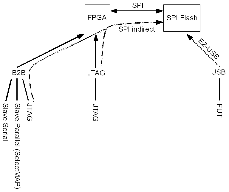 |
| TE0320 | 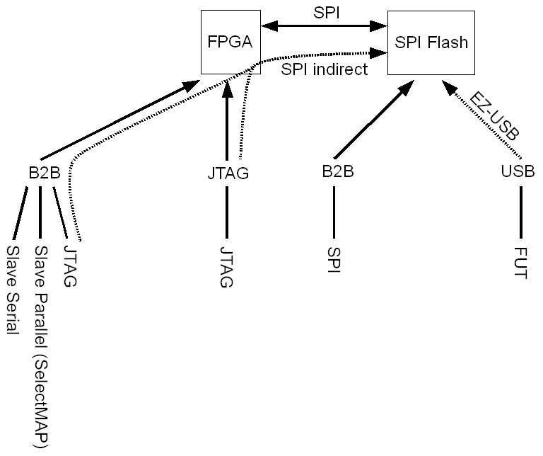 |
| TE0300 | 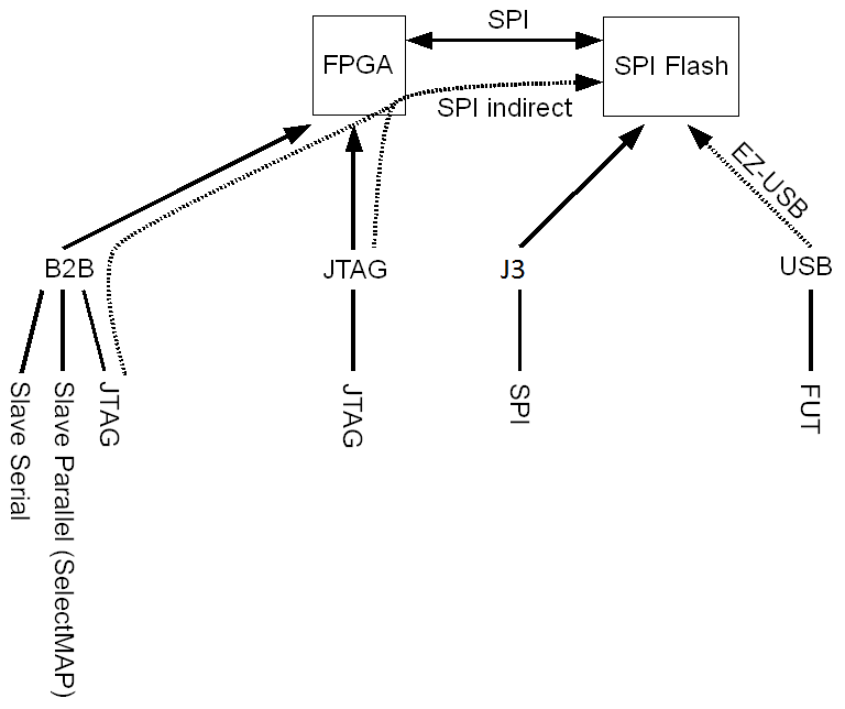 |
Configuration modes overview: FPGA bitstream only.
USB interface
TE USB FX2 module is equipped with a Cypress EZ-USB FX2 controller (TE USB FX2 microcontroller) to provide a high-speed USB 2.0 interface. Configuration of the TE USB FX2 module through a USB host is recommended for non-volatile on-site operations such as firmware upgrade or SPI Flash bitstream download.
Even when USB connector is used to program the FPGA image (aka FPGA bitstream), the SPI bus and the the SPI Flash memory are also used by C# OpenFutNet or Python Open_FUT.
The procedure followed by one of the two TE programs (or by a custom user program) is the following:
Even when USB connector is used to program the FX2 microcontroller's firmware, the IIC bus and the the IIC EEPROM memory are also used by C# OpenFutNet or Python Open_FUT.
Jtag Interface
The JTAG interface allows a
- fast (10 seconds), frequent but volatile configuration (only the FPGA is programmed using Xilinx ISE or EDK and a .bit bitstream and not the SPI Flash) of the TE USB FX2 module.
- medium-fast (1-2 minutes) non-volatile on-site operations such as SPI Flash bitstream download: indirect SPI in-system programming (ISP).
Only through the JTAG interface it is possible to develop and debug with Xilinx tools (e.g. Xilinx SDK debug,Xilinx ChipScope, Xilinx Microprocessor Debugger).
SPI Interface
SPI interfaces allows a medium-fast (1-2 minutes), frequent and non-volatile configuration (SPI Flash bitstream download) of the TE0300 module (through J3 and direct SPI programming or TE USB FX2 microcontroller and OpenFutNet), TE0320 module (through B2B connection or TE USB FX2 microcontroller and OpenFutNet), TE0630 module (through TE USB FX2 microcontroller and OpenFutNet).
B2B Interface
Through B2B interface JTAG and/or SPI interface could be used (see the two paragraphes above).
It is also possible to use B2B interface for
- Slave Paralellel (SelectMAP)
- Slave Serial
configurations.
Interface Available to FX2 microcontroller
The FX2 microcontroller uses 4 interfaces (see here):
- USB interface (to USB connector): connection with the host computer;
- I2C interface (to EEPROM): the I2C interface connects the USB controller to the EEPROM chip, which stores vendor ID and device ID and the USB firmware. See chapter DIP Switch for available options.
- SPI interface (to FPGA and Flash): the SPI interface is used to communicate with the FPGA and to access the SPI serial Flash chip. The SPI interface allows a medium-fast (1-2 minutes), frequent and non-volatile configuration (SPI Flash bitstream download) through TE USB FX2 microcontroller and OpenFutNet;
- B2B interface;
- FIFO interface (to FPGA): the FIFO interface provides a high-speed communication channel with the FPGA.The interface can transfer up to 48 MB/s burst rate.
JTAG interface is not directly available to FX2 microcontroller.
Overview
Content Tools