Table of Contents
TEBF0808 with TE080x
Overview
Basic instructions to work with TEBF0808 and TE0808,TE0807 or TE0803.
Functionality of buttons, DIP switches, LEDs depends on CPLD Firmware. Following description is only for newest firmware version, which is available on the download area
Board Overview
| Number | Note | Letter | Note | |
|---|---|---|---|---|
| 1 | S2- Reset Button | A | P1 - PMOD 3.3V I2C Bus | |
| 2 | D7 - LED D7 Red (Usage: status) || D6 - LED Green (Usage: status) | B | J9 - Audio Enclosure | |
| 3 | S1 - Power Button | C | J26 - FAN1 12V | |
| 4 | J25 - Power Jack J25, 2.1mm (optional 12V power input) | D | J17 - I2C (for optional module PLL access) | |
| 5 | S5 - DIP Switch for Boot Mode and FMCVADJ | E | J6/15 - Firefly - GTH | |
| 6 | J10 - Enclosure Pin header(Reset and Power Button, HD LED (Usage: status/user) and Power LED (Usage: status/user)) | F | J31 - SATA | |
| 7 | S4 - DIP Switch for CPLD access and power control | G | J21/22 - Firefly - loopback only | |
| 8 | J12 - XMOD with green dot for Module JTAG and UART, XMOD LED D4 Red used for status information | H | P3 - PMOD 3.3V I2C Bus | |
| 9 | J28 - XMOD for CPLD,FMC JTAG and Firmware ID over UART(need CPLD Firmware 7 or newer) , XMOD LED D4 Red used for status information | I | J34 - I2C Firefly | |
| 10 | FPGA Done LED (location varies slightly on different module series ) | J | J35 - FAN2 12V | |
| 11 | J20 - ATX Power Connector (Main 12V and 5V Power supply), recommended power supply connector | K | J11 - PCIe (1x) | |
| 12 | D1 - SFP LED Red (Usage: status/user) | L | B1 - Battery holder CR1220 | |
| 13 | D8 - SFP LED Green (Usage: status/user) | M | J30 - PJTAG | |
| 14 | D9 - SFP LED Red (Usage: status/user) | N | J29 - CAN (same as J24) | |
| 15 | D10 - SFP LED Green (Usage: status/user) | O | J5 - FMC HPC | |
| 16 | J7 - ETH LED Yellow (Usage: status) | P | J19 - FAN3 5V | |
| 17 | J7 - ETH LED Green/Orange (Usage: status) | Q | J24 - CAN (same as J29) | |
| 18 | D4 - LED Green (Usage: status/user) || D5 - LED Red (Usage: status/user) | R | J27 - SD | |
| --- | --- | S | J8 - USB 3.0 (2x) Enclosure | |
| --- | --- | T | J14 - SFP (2x) | |
| --- | --- | U | J7 - USB 3.0 (2x), ETH (1x) | |
| --- | --- | V | J13 - Displayport (1x) | |
| --- | --- | W | P2 - PMOD 3.3V FPG IOs | |
| --- | --- | W(b) | Bottom side: J16 - microSD |
Power supply
| Label | Designator | Power | Description |
|---|---|---|---|
| Overview - 12 | J20 | 12V and 5V | Recommended power supply unit is PC power supply unit:
|
| Overview - 4 | J25 | 12V | Optional single 12V power supply:
|
Current depends manly on design and cooling solution. Use Xilinx Power Estimator and/or Your Vivado Project to estimate min current. Minimum of 3A are recommanded for basic functionality.
DIP-Switches and Push Buttons
| Overview 7 | Default | Description |
|---|---|---|
| S4-1 | OFF | SoC PUDC, ON (low - internal FPGA pull ups enabled), OFF (high - internal FPGA pull ups disabled) |
| S4-2 | OFF | N.C. |
| S4-3 | OFF | JTAGEN ON (CPLD access), OFF (FMC access) |
| S4-4 | ON | Enable on board 5V permanently |
DIP Switches S4
| Overview 5 | Default | Description |
|---|---|---|
| S5-1 | ON |
|
| S5-2 | ON | |
| S5-3 | OFF | User Input to SoC over RGPIO interface |
| S5-4 | OFF | VADJ OFF(1.8V), ON(1.2V) |
DIP Switches S5 (CPLD Firmware depended)
| Overview 1;3;6 | Default | Description |
|---|---|---|
| S1 | High | Negative Reset Button, alternative Enclosure over J10-7/J10-5
|
| S2 | High | Negative Power Button, alternative Enclosure over J10-6/J10-8
|
Buttons (CPLD Firmware depended)
LEDs
LEDs used different Blink Sequence to indicate all state:
| Blink Sequence | Frequence | Note |
|---|---|---|
| ******** (slow blinking) | ~0,7 Hz | continuous blinking, like SFP LEDs or Enclosure HD LED when board is powered down |
| ******** (fast blinking) | ~5,8 Hz | continuous blinking, like D6 LED or Enclosure Power LED when board is powered down |
| *****ooo | ~0,7 Hz, duty cycle 5/8 | 5 times fast blink with a break |
| ****oooo | ~0,7 Hz, duty cycle 4/8 | 4 times fast blink with a break |
| ***ooooo | ~0,7 Hz, duty cycle 3/8 | 3 times fast blink with a break |
| **oooooo | ~0,7 Hz, duty cycle 2/8 | 2 times fast blink with a break |
| *ooooooo | ~0,7 Hz, duty cycle 1/8 | 1 times fast blink with a break |
| ON | --- | LED ON |
| OFF | --- | LED OFF |
LED Sequencing (CPLD Firmware depended)
| Label | Designator | Color | Usage | Description | ||||||||||||||||||||||||||||||||||||||||||||||||||||||||||||
|---|---|---|---|---|---|---|---|---|---|---|---|---|---|---|---|---|---|---|---|---|---|---|---|---|---|---|---|---|---|---|---|---|---|---|---|---|---|---|---|---|---|---|---|---|---|---|---|---|---|---|---|---|---|---|---|---|---|---|---|---|---|---|---|---|
| Overview - 2 | D7 | Red | status |
| ||||||||||||||||||||||||||||||||||||||||||||||||||||||||||||
| Overview - 2 | D6 | Green | status |
| ||||||||||||||||||||||||||||||||||||||||||||||||||||||||||||
| Overview - 6 | J10 Power LED | Blue (symbol light bulb) | status/user |
| ||||||||||||||||||||||||||||||||||||||||||||||||||||||||||||
| Overview - 6 | J10 HD LED | Red (symbol drive) | status/user |
| ||||||||||||||||||||||||||||||||||||||||||||||||||||||||||||
| Overview - 8 | XMOD1 D4 | Red | status |
| ||||||||||||||||||||||||||||||||||||||||||||||||||||||||||||
| Overview - 9 | XMOD2 D4 | Red | status/user |
| ||||||||||||||||||||||||||||||||||||||||||||||||||||||||||||
| Overview - 12 | SFP D1 | Red | status/user |
| ||||||||||||||||||||||||||||||||||||||||||||||||||||||||||||
| Overview - 13 | SFP D8 | Green | status/user |
| ||||||||||||||||||||||||||||||||||||||||||||||||||||||||||||
| Overview - 14 | SFP D9 | Red | status/user |
| ||||||||||||||||||||||||||||||||||||||||||||||||||||||||||||
| Overview - 15 | SFP D10 | Green | status/user |
| ||||||||||||||||||||||||||||||||||||||||||||||||||||||||||||
| Overview - 16 | ETH J7 | Yellow | status |
| ||||||||||||||||||||||||||||||||||||||||||||||||||||||||||||
| Overview - 17 | ETH J7 | Green/Orange | status |
| ||||||||||||||||||||||||||||||||||||||||||||||||||||||||||||
| Overview - 18 | D4 | Green | status/user |
| ||||||||||||||||||||||||||||||||||||||||||||||||||||||||||||
| Overview - 18 | D5 | Red | status/user |
|
Carrier LEDs (CPLD Firmware depended)
| Label | Designator | Color | Connected to | Description |
|---|---|---|---|---|
| Overview - 10 | D1 | Red | DONE signal (PS Configuration Bank 503) | This LED goes ON when power has been applied to the module and stays ON until MPSoC's programmable logic is configured properly. |
Module LEDs
JTAG/UART
| Label | Designator | Description |
|---|---|---|
| Overview - 8 | J12 |
|
| Overview - 9 | J28 |
|
DIP Switch on bouth XMOD JTAG adapters must be set like on the following table.
| XMOD DIP Switch | Setting |
|---|---|
| 1 | ON |
| 2 | OFF |
| 3 | OFF |
| 4 | OFF |
XMOD JTAG DIP Switch. Attention: Never changes the default setting
For more information refer to TE0790.
CPLD Firmware
Firmware Update Instruction and CPLD description are available on TEBF0808 CPLD Firmware. Source code of the firmware is available on the download area of the TEBF0808.
Firmware Versions and some statistics can be displayed over second XMOD:
- Included since CPLD Firmware Update to REV07
- UART Speed is 115200
- Press XMOD Button to see output, otherwise RX/TX are loop backed
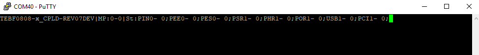
CPLD Firmware ID
| Type | Description |
|---|---|
| TE0808-x_CPLD-REV07 | CPLD Firmware Version |
| MP |
|
| PIN |
|
| PEE |
|
| PES |
|
| PSR |
|
| PHR |
|
| POR |
|
| USB |
|
| PCI |
|
CPLD Firmware and Statistic over UART
Reference Designs
Link to different Reference Designs (Descriptions and Download)
It's recommended to use prebuilt Boot.bin and image.ub of newest Starterkit Reference Design for first test. Basic Steps:
- Power Supply over ATX, optional 12V power jack
- Download Reference Design
- Copy Boot.bin and image.ub on SD
- Connect USB to XMOD with Green Dot
- Open Putty
- Set Boot Mode to SD, set DIP S5-1 and S5-2 to ON (Overview 5) and inserted SD with Design on SD Slot (Overview R)
- Press Power Button on Enclosure or on Carrier (Overview 3)
- For more detailed check Reference Design description
Notes
Module and Carrier are also as starter kit available:
Links to all documentation and download resources:
Overview
Content Tools