Design Name is always "TE Series Name" + Design name, for example "TE0720 Test Board"
|
Important General Note:
|
Overview
Notes :
|
Demonstration design for the CRUVI module board CR00200 in combination with the carrier board TEB0707-02 and the module board TE0821. The design implements a Linux example with web server application suitable for ZynqMP access via the Ethernet interface of the CRUVI module. The signals implemented in the VIO can be displayed and controlled by the Vivado HW-Manager.
Wiki Resources page: http://trenz.org/te0821-info
Key Features
Notes :
|
|
Revision History
Notes :
|
|
Release Notes and Know Issues
Notes :
|
|
Requirements
Software
Notes :
|
|
Hardware
Notes :
|
Design supports following modules:
*used as reference |
Design supports following carriers:
*used as reference |
Additional HW Requirements:
*used as reference |
Content
Notes :
|
For general structure and of the reference design, see Project Delivery - AMD devices
Design Sources
|
Additional Sources
|
Prebuilt
Notes :
|
|
Download
Reference Design is only usable with the specified Vivado/Vitis/PetaLinux version. Do never use different Versions of Xilinx Software for the same Project.
|
Reference Design is available on:
Design Flow
Notes :
|
Reference Design is available with and without prebuilt files. It's recommended to use TE prebuilt files for first launch. |
Trenz Electronic provides a tcl based built environment based on Xilinx Design Flow.
See also:
The Trenz Electronic FPGA Reference Designs are TCL-script based project. Command files for execution will be generated with "_create_win_setup.cmd" on Windows OS and "_create_linux_setup.sh" on Linux OS.
TE Scripts are only needed to generate the vivado project, all other additional steps are optional and can also executed by Xilinx Vivado/Vitis GUI. For currently Scripts limitations on Win and Linux OS see: Project Delivery Currently limitations of functionality
Caution! Win OS has a 260 character limit for path lengths which can affect the Vivado tools. To avoid this issue, use Virtual Drive or the shortest possible names and directory locations for the reference design (for example "x:\<project folder>") |
Run _create_win_setup.cmd/_create_linux_setup.sh and follow instructions on shell:
------------------------Set design paths----------------------------
-- Run Design with: _create_win_setup
-- Use Design Path: <absolute project path>
--------------------------------------------------------------------
-------------------------TE Reference Design---------------------------
--------------------------------------------------------------------
-- (0)  Module selection guide, project creation...prebuilt export...
-- (1)  Create minimum setup of CMD-Files and exit Batch
-- (2)  Create maximum setup of CMD-Files and exit Batch
-- (3)  (internal only) Dev
-- (4)  (internal only) Prod
-- (c)  Go to CMD-File Generation (Manual setup)
-- (d)  Go to Documentation (Web Documentation)
-- (g)  Install Board Files from Xilinx Board Store (beta)
-- (a)  Start design with unsupported Vivado Version (beta)
-- (x)  Exit Batch (nothing is done!)
----
Select (ex.:'0' for module selection guide):
Press 0 and enter to start "Module Selection Guide"
Create project and follow instructions of the product selection guide, settings file will be configured automatically during this process.
optional for manual changes: Select correct device and Xilinx install path on "design_basic_settings.cmd" and create Vivado project with "vivado_create_project_guimode.cmd"
Note: Select correct one, see also Vivado Board Part Flow
Create hardware description file (.xsa file) for PetaLinux project and export to prebuilt folder
TE::hw_build_design -export_prebuilt
Using Vivado GUI is the same, except file export to prebuilt folder.
Create and configure your PetaLinux project with exported .xsa-file, see PetaLinux KICKstart
use TE Template from "<project folder>\os\petalinux"
use exported .xsa file from "<project folder>\prebuilt\hardware\<short name>" . Note: HW Export from Vivado GUI creates another path as default workspace.
The build images are located in the "<plnx-proj-root>/images/linux" directory
Configure the boot.scr file as needed, see Distro Boot with Boot.scr
Copy PetaLinux build image files to prebuilt folder
copy u-boot.elf, system.dtb, image.ub, bl31.elf and boot.scr from "<plnx-proj-root>/images/linux" to prebuilt folder
"<project folder>\prebuilt\os\petalinux\<ddr size>" or "<project folder>\prebuilt\os\petalinux\<short name>"
This step depends on Xilinx Device/Hardware
for Zynq-7000 series
- copy u-boot.elf, u-boot.dtb, system.dtb, image.ub and boot.scr from "<plnx-proj-root>/images/linux" to prebuilt folder
for ZynqMP
- copy u-boot.elf, u-boot.dtb, system.dtb, bl31.elf, image.ub and boot.scr from "<plnx-proj-root>/images/linux" to prebuilt folder
for Microblaze
- ...
Generate Programming Files with Vitis
TE::sw_run_vitis -all
TE::sw_run_vitis (optional; Start Vitis from Vivado GUI or start with TE Scripts on Vivado TCL)
TCL scripts generate also platform project, this must be done manually in case GUI is used. See Vitis
Launch
Note:
|
Programming
Check Module and Carrier TRMs for proper HW configuration before you try any design. Reference Design is also available with prebuilt files. It's recommended to use TE prebuilt files for first launch. |
Xilinx documentation for programming and debugging: Vivado/Vitis/SDSoC-Xilinx Software Programming and Debugging
Note: Depending on CPLD Firmware and Boot Mode settings, QSPI boot with Linux image on SD or complete SD Boot is possible.
Get prebuilt boot binaries
Run _create_win_setup.cmd/_create_linux_setup.sh and follow instructions on shell
Press 0 and enter to start "Module Selection Guide"
Select assembly version
Validate selection
Select Create and open delivery binary folder
Note: Folder "<project folder>\_binaries_<Article Name>" with subfolder "boot_<app name>" for different applications will be generated
SD-Boot mode
Copy image.ub, boot.src and Boot.bin on SD
use files from "<project folder>\_binaries_<Article Name>\boot_linux" from generated binary folder, see: Get prebuilt boot binaries
or use prebuilt file location, see "<project folder>\prebuilt\file_location.txt"
Set Boot Mode to SD-Boot.
Depends on Carrier, see carrier TRM.
Insert SD-Card in SD-Slot.
JTAG
Not used on this Example.
Usage
Prepare HW like described on section Programming
Connect UART USB (most cases same as JTAG)
Select SD Card or QSPI as Boot Mode (Depends on used programming variant)
Note: See TRM of the Carrier, which is used.
Starting with Petalinux version 2020.1, the industry standard "Distro-Boot" boot flow for U-Boot was introduced, which significantly expands the possibilities of the boot process and has the primary goal of making booting much more standardised and predictable.
The boot options described above describe the common boot processes for this hardware; other boot options are possible.
For more information see Distro Boot with Boot.scrPower On PCB
1. ZynqMP Boot ROM loads PMU Firmware and FSBL from SD/QSPI Flash into OCM
2. FSBL init PS, programs PL using the bitstream and loads U-boot from SD into DDR,
3. U-boot loads Linux (image.ub) from SD/QSPI/... into DDR
Linux
Open Serial Console (e.g. putty)
Speed: 115200
Select COM Port
Win OS, see device manager, Linux OS see dmesg |grep tty (UART is *USB1)
Linux Console:
# password default disabled with 2021.2 petalinux release
petalinux login: root
Password: root
Note: Wait until Linux boot finished
You can use Linux shell now.
Ethernet
	ifconfig		 	(display all active interface details)
Option Features
Webserver to get access to Zynq
insert IP on web browser to start web interface
init.sh scripts
add init.sh script on SD, content will be load automatically on startup (template included in "<project folder>\misc\SD")
Vivado HW Manager
Note:
|
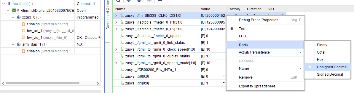
Monitoring:
SI5338_CLKx Counter:
Set radix from VIO signals to unsigned integer.
Note: Frequency Counter is inaccurate and displayed unit is Hz for CLK signals
SI5338 CLK0 is configured to 200MHz by default and SI5338 CLK3 is configured to 125MHz by default.
- CR00200_Phy_CLK125 measured CRUVI Phy CLK125 clock signal with 125MHz
- GMII_to_RGMII output signals
- link status
- clock speed
- duplex_status
- speed_mode
- CR00200_Phy Interrupt Signal
Control:
LED over X0/X1 , see TE0821 CPLD#LED
|
System Design - Vivado
Note:
|
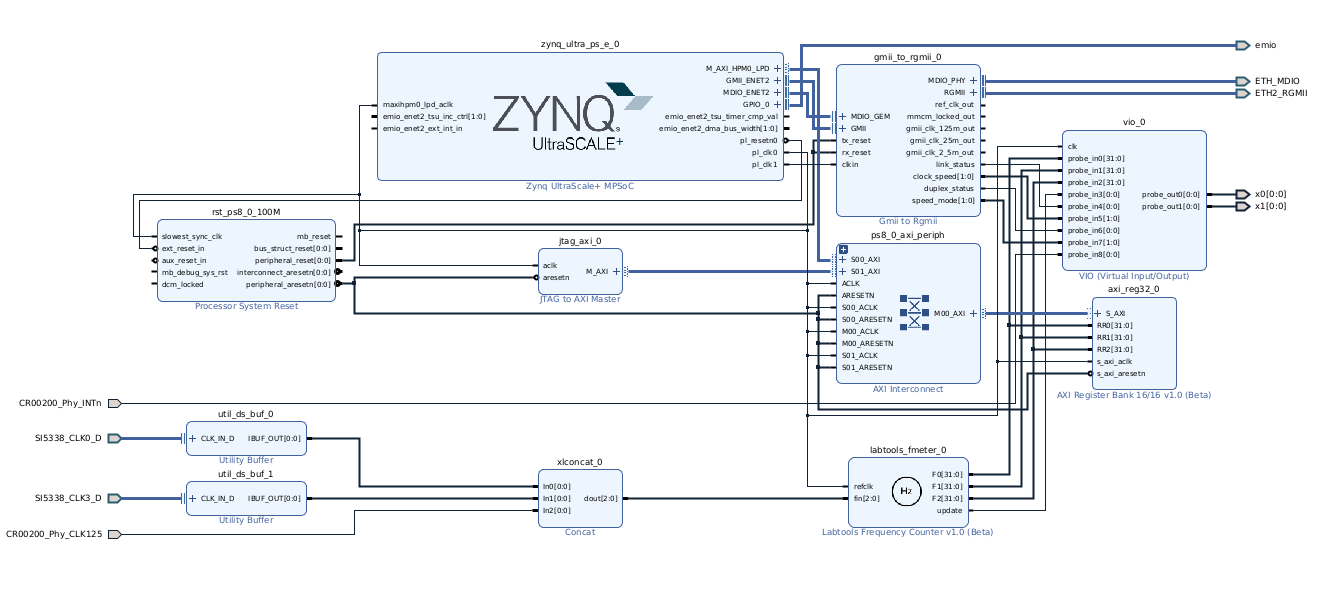
Block Design
|
PS Interfaces
Note:
|
Activated interfaces:
|
Constrains
Basic module constrains
set_property BITSTREAM.GENERAL.COMPRESS TRUE [current_design] set_property BITSTREAM.CONFIG.UNUSEDPIN PULLNONE [current_design] |
Design specific constrain
#SI5338
set_property PACKAGE_PIN E5 [get_ports {SI5338_CLK0_D_clk_p[0]}]
set_property IOSTANDARD LVDS [get_ports {SI5338_CLK0_D_clk_p[0]}]
set_property PACKAGE_PIN C3 [get_ports {SI5338_CLK3_D_clk_p[0]}]
set_property IOSTANDARD LVDS [get_ports {SI5338_CLK3_D_clk_p[0]}]


#CPLD
set_property PACKAGE_PIN B1 [get_ports {x0[0]}]
set_property IOSTANDARD LVCMOS18 [get_ports {x0[0]}]
set_property PACKAGE_PIN C1 [get_ports {x1[0]}]
set_property IOSTANDARD LVCMOS18 [get_ports {x1[0]}]


#Ethernet
#IO Placement
set_property PACKAGE_PIN R7 [get_ports {emio_tri_io[0]}]
set_property IOSTANDARD LVCMOS18 [get_ports {emio_tri_io[0]}]

set_property PACKAGE_PIN T7 [get_ports {CR00200_Phy_INTn}]
set_property IOSTANDARD LVCMOS18 [get_ports {CR00200_Phy_INTn}]

set_property PACKAGE_PIN L3 [get_ports {CR00200_Phy_CLK125}]
set_property IOSTANDARD LVCMOS18 [get_ports {CR00200_Phy_CLK125}]

#CR00200 --> TEB0707 J11 --> TE0821
set_property PACKAGE_PIN N9 [get_ports {ETH2_RGMII_txc}]
set_property PACKAGE_PIN N8 [get_ports {ETH2_RGMII_tx_ctl}]
set_property PACKAGE_PIN M8 [get_ports {ETH2_RGMII_td[0]}]
set_property PACKAGE_PIN L8 [get_ports {ETH2_RGMII_td[1]}]
set_property PACKAGE_PIN K7 [get_ports {ETH2_RGMII_td[2]}]
set_property PACKAGE_PIN K8 [get_ports {ETH2_RGMII_td[3]}]
set_property PACKAGE_PIN K4 [get_ports {ETH2_RGMII_rxc}]
set_property PACKAGE_PIN K3 [get_ports {ETH2_RGMII_rx_ctl}]
set_property PACKAGE_PIN M6 [get_ports {ETH2_RGMII_rd[0]}]
set_property PACKAGE_PIN L5 [get_ports {ETH2_RGMII_rd[1]}]
set_property PACKAGE_PIN P7 [get_ports {ETH2_RGMII_rd[2]}]
set_property PACKAGE_PIN P6 [get_ports {ETH2_RGMII_rd[3]}]

set_property PACKAGE_PIN Y8 [get_ports {ETH_MDIO_mdc}]
set_property PACKAGE_PIN W8 [get_ports {ETH_MDIO_mdio_io}]

set_property IOSTANDARD LVCMOS18 [get_ports {ETH2_RGMII_*}]
set_property IOSTANDARD LVCMOS18 [get_ports {ETH_MDIO_*}]

set_property PULLTYPE PULLUP [get_ports {ETH2_RGMII_*}]
set_property PULLTYPE PULLUP [get_ports {ETH_MDIO_*}]

#set_property slew FAST [get_ports {ETH2_RGMII_*}]
#set_property slew FAST [get_ports {ETH_MDIO_*}]


# Clock Period Constraints
create_clock -period 8.000 -name ETH2_RGMII_rxc -add [get_ports ETH2_RGMII_rxc]

## Use these constraints to modify output delay on RGMII signals if 2ns delay is added by external PHY
#set_output_delay -clock [get_clocks ETH2_RGMII_txc] -max -1.0 [get_ports {ETH2_RGMII_td[*] ETH2_RGMII_txc}]
#set_output_delay -clock [get_clocks ETH2_RGMII_txc] -min -2.6 [get_ports {ETH2_RGMII_td[*] ETH2_RGMII_txc}] -add_delay
#set_output_delay -clock [get_clocks ETH2_RGMII_txc] -clock_fall -max -1.0 [get_ports {ETH2_RGMII_td[*] ETH2_RGMII_txc}]
#set_output_delay -clock [get_clocks ETH2_RGMII_txc] -clock_fall -min -2.6 [get_ports {ETH2_RGMII_td[*] ETH2_RGMII_txc}]

#clock setting
set_property UNAVAILABLE_DURING_CALIBRATION TRUE [get_ports ETH2_RGMII_td[1]]
set_property UNAVAILABLE_DURING_CALIBRATION TRUE [get_ports ETH_MDIO_mdio_io]


##clock setting
##set_property CLOCK_DEDICATED_ROUTE FALSE [get_nets zusys_i/gmii_to_rgmii_0/U0/i_gmii_to_rgmii_block/rgmii_rxc_ibuf_i/O]
#set_property UNAVAILABLE_DURING_CALIBRATION TRUE [get_ports ETH2_RGMII_td[1]]


##False path constraints to async inputs coming directly to synchronizer
#set_false_path -to [get_pins -hier -filter {name =~ *idelayctrl_reset_gen/*reset_sync*/PRE }]
#set_false_path -to [get_pins -of [get_cells -hier -filter { name =~ *i_MANAGEMENT/SYNC_*/data_sync* }] -filter { name =~ *D }]
#set_false_path -to [get_pins -hier -filter {name =~ *reset_sync*/PRE }]

##False path constraints from Control Register outputs
#set_false_path -from [get_pins -hier -filter {name =~ *i_MANAGEMENT/DUPLEX_MODE_REG*/C }]
#set_false_path -from [get_pins -hier -filter {name =~ *i_MANAGEMENT/SPEED_SELECTION_REG*/C }]

## constraint valid if parameter C_EXTERNAL_CLOCK = 0
#set_case_analysis 0 [get_pins -hier -filter {name =~ *i_bufgmux_gmii_clk/CE0}]
#set_case_analysis 0 [get_pins -hier -filter {name =~ *i_bufgmux_gmii_clk/S0}]
#set_case_analysis 1 [get_pins -hier -filter {name =~ *i_bufgmux_gmii_clk/CE1}]
#set_case_analysis 1 [get_pins -hier -filter {name =~ *i_bufgmux_gmii_clk/S1}]

## constraint valid if parameter C_EXTERNAL_CLOCK = 0 and clock skew on TXC is through MMCM
#set_case_analysis 0 [get_pins -hier -filter {name =~ *i_bufgmux_gmii_90_clk/CE0}]
#set_case_analysis 0 [get_pins -hier -filter {name =~ *i_bufgmux_gmii_90_clk/S0}]
#set_case_analysis 1 [get_pins -hier -filter {name =~ *i_bufgmux_gmii_90_clk/CE1}]
#set_case_analysis 1 [get_pins -hier -filter {name =~ *i_bufgmux_gmii_90_clk/S1}]

##These constraints are for non-Versal devices
##To Adjust GMII Rx Input Setup/Hold Timing
#set_property IDELAY_VALUE 16 [get_cells *delay_rgmii_rx_ctl]
#set_property IDELAY_VALUE 16 [get_cells -hier -filter {name =~ *delay_rgmii_rxd*}]
#set_property IODELAY_GROUP gpr1 [get_cells *delay_rgmii_rx_ctl]
#set_property IODELAY_GROUP gpr1 [get_cells -hier -filter {name =~ *delay_rgmii_rxd*}]
#set_property IODELAY_GROUP gpr1 [get_cells *idelayctrl]

#set_property slew FAST [get_ports [list {ETH2_RGMII_td[3]} {ETH2_RGMII_td[2]} {ETH2_RGMII_td[1]} {ETH2_RGMII_td[0]} ETH2_RGMII_txc ETH2_RGMII_tx_ctl]]

#clock setting
#set_property CLOCK_DEDICATED_ROUTE FALSE [get_nets zusys_i/gmii_to_rgmii_0/U0/i_gmii_to_rgmii_block/rgmii_rxc_ibuf_i/O]
|
Software Design - Vitis
Note:
|
For Vitis project creation, follow instructions from:
Application
---------------------------------------------------------- FPGA Example scuMCS Firmware to configure SI5338 and Reset System. srec_spi_bootloaderTE modified 2021.2 SREC Bootloader to load app or second bootloader from flash into DDR Descriptions:
xilisf_v5_11TE modified 2021.2 xilisf_v5_11
---------------------------------------------------------- Zynq Example: fsblTE modified 2021.2 FSBL General:
Module Specific:
fsbl_flashTE modified 2021.2 FSBL General:
ZynqMP Example: ---------------------------------------------------------- zynqmp_fsblTE modified 2021.2 FSBL General:
Module Specific:
zynqmp_fsbl_flashTE modified 2021.2 FSBL General:
zynqmp_pmufwXilinx default PMU firmware. ---------------------------------------------------------- General Example: hello_te0820Hello TE0820 is a Xilinx Hello World example as endless loop instead of one console output. u-bootU-Boot.elf is generated with PetaLinux. Vitis is used to generate Boot.bin. |
Template location: "<project folder>\sw_lib\sw_apps\"
zynqmp_fsbl
TE modified 2021.2 FSBL
General:
- Modified Files: xfsbl_main.c, xfsbl_hooks.h/.c, xfsbl_board.h/.c (search for 'TE Mod' on source code)
- Add Files: te_xfsbl_hooks.h/.c (for hooks and board)
- General Changes:
- Display FSBL Banner and Device Name
Module Specific:
- Add Files: all TE Files start with te_*
- Si5338 Configuration
- ETH+OTG Reset over MIO
zynqmp_fsbl_flash
TE modified 2021.2 FSBL
General:
- Modified Files: xfsbl_initialisation.c, xfsbl_hw.h, xfsbl_handoff.c, xfsbl_main.c
- General Changes:
- Display FSBL Banner
- Set FSBL Boot Mode to JTAG
- Disable Memory initialisation
zynqmp_pmufw
Xilinx default PMU firmware.
hello_te0821
Hello TE0821 is a Xilinx Hello World example as endless loop instead of one console output.
u-boot
U-Boot.elf is generated with PetaLinux. Vitis is used to generate Boot.bin.
Software Design - PetaLinux
Note:
|
For PetaLinux installation and project creation, follow instructions from:
Config
Start with petalinux-config or petalinux-config --get-hw-description
Changes:
- select SD default instead of eMMC:
- CONFIG_SUBSYSTEM_PRIMARY_SD_PSU_SD_1_SELECT=y
- add new flash partition for bootscr and sizing
- CONFIG_SUBSYSTEM_FLASH_PSU_QSPI_0_BANKLESS_PART0_SIZE=0x2000000
- CONFIG_SUBSYSTEM_FLASH_PSU_QSPI_0_BANKLESS_PART2_SIZE=0x2000000
- CONFIG_SUBSYSTEM_FLASH_PSU_QSPI_0_BANKLESS_PART3_NAME="bootscr"
- CONFIG_SUBSYSTEM_FLASH_PSU_QSPI_0_BANKLESS_PART3_SIZE=0x80000
- select PSU_ethernet_2 instead of PSU_ethernet_3
- CONFIG_SUBSYSTEM_ETHERNET_PSU_ETHERNET_2_SELECT=y
U-Boot
Start with petalinux-config -c u-boot
Changes:
- MAC from eeprom together with uboot and device tree settings:
- CONFIG_ENV_OVERWRITE=y
- Boot Modes:
- CONFIG_QSPI_BOOT=y
- CONFIG_SD_BOOT=y
- # CONFIG_ENV_IS_IN_NAND is not set
- CONFIG_BOOT_SCRIPT_OFFSET=0x4040000
Change platform-top.h:
#include <configs/xilinx_zynqmp.h> #no changes |
Device Tree
/include/ "system-conf.dtsi"
#include <dt-bindings/gpio/gpio.h>
/ {
  chosen {
    xlnx,eeprom = &eeprom;
  };
};

/*------------------------- QSPI ------------------------- */
&qspi {
    #address-cells = <1>;
    #size-cells = <0>;
    status = "okay";
    flash0: flash@0 {
        //compatible = "flash name, "micron,m25p80";
        compatible = "jedec,spi-nor";
        reg = <0x0>;
        #address-cells = <1>;
        #size-cells = <1>;
    };
};


/*----------------------- SD1 sd2.0 -----------------------*/
&sdhci1 {
    disable-wp;
    no-1-8-v;
};

/*------------------------- ETH PHY -----------------------*/
/delete-node/ &psu_ethernet_2_mdio;
&gem2 {
    phy-handle = <&phy1_gem2>;
    phy-mode = "rgmii-id";
    status = "okay";

    reset-names = "ETH_RST";
    reset-gpios = <&gpio 78 GPIO_ACTIVE_LOW>;

    phy1_gem2: ethernet-phy@1 {
        device_type = "ethernet-phy";
        reg = <1>;
    };

    rgmii_0: rgmii_0@4 {
        phy-handle = <&phy1_gem2>;
        compatible = "xlnx,gmii-to-rgmii-1.0";
        reg = <4>;
    };
};


/*----------------------- USB 2.0 only --------------------*/
&dwc3_0 {
    status = "okay";
    dr_mode = "host";
    maximum-speed = "high-speed";
    /delete-property/phy-names;
    /delete-property/phys;
    /delete-property/snps,usb3_lpm_capable;
    snps,dis_u2_susphy_quirk;
    snps,dis_u3_susphy_quirk;
};

&usb0 {
    status = "okay";
    /delete-property/ clocks;
    /delete-property/ clock-names;
    clocks = <0x3 0x20>;
    clock-names = "bus_clk";
};

/*---------------------------- I2C ------------------------*/
&i2c0 {
  eeprom: eeprom@50 {
     compatible = "microchip,24aa025", "atmel,24c02";
     reg = <0x50>;
  };
};
|
Kernel
Start with petalinux-config -c kernel
Changes:
Only needed to fix JTAG Debug issue:
CONFIG_CPU_IDLE is not set
CONFIG_CPU_FREQ is not set
- CONFIG_EDAC_CORTEX_ARM64=y
Rootfs
Start with petalinux-config -c rootfs
Changes:
- For web server app:
- CONFIG_busybox-httpd=y
- For additional test tools only:
- CONFIG_i2c-tools=y
- CONFIG_packagegroup-petalinux-utils=y (util-linux,cpufrequtils,bridge-utils,mtd-utils,usbutils,pciutils,canutils,i2c-tools,smartmontools,e2fsprogs)
Applications
See "<project folder>\os\petalinux\project-spec\meta-user\recipes-apps\"
startup
Script App to load init.sh from SD Card if available.webfwu
Webserver application suitable for Zynq access. Need busybox-httpd
Additional Software
Note: |
SI5338
File location "<project folder>\misc\PLL\Si5338_B\Si5338-*.slabtimeproj"
General documentation how you work with these project will be available on Si5338
Appx. A: Change History and Legal Notices
Document Change History
To get content of older revision got to "Change History" of this page and select older document revision number.
|
|
Legal Notices
|
<style>
.wiki-content .columnLayout .cell.aside {
width: 20%;
}</style>
|
|