Direct SPI configuration is supported only up to Xilinx iMPACT version 11.x. See Xilinx AR#36156. Available only for TE0300 (through J3 SPI interface) and TE0320 (through B2B connection).
For further information about direct (pure SPI) in-system programming of SPI Flash memories, please see Xilinx Application Note XAPP951 "Configuring Xilinx FPGAs with SPI Serial Flash".
You must follow the procedure below.
Make sure that reset swith is enabled:
- S2 is switched to "Reset" (OFF) during programming (TE0300 module);
- S1D is switched to "Reset" (ON) during programming (TE0320 module).
Connect the host computer to the micromodule through both the SPI flying leads cable and the USB cable.
Start Xilinx ISE iMPACT. The following example shows the case of iMPACT 9.2. If the "iMPACT Project" window pops up, press the "Cancel" button.

"iMPACT Project" window pops up
Double click the "Direct SPI Configuration" option in the "Modes" panel.

"Direct SPI Configuration" option in the "Modes" panel.
Right click the "Direct SPI Configuration" panel to add a device and select "Add SPI Device".


Right click the "Direct SPI Configuration" panel to add a device and select "Add SPI Device"
You can now select the file corresponding to your device. In the following example, we will show how to select the micromodule reference device "blinking.mcs" in the "TE0300" folder.

select the micromodule reference device "blinking.mcs" in the "TE0300" folder
Select the part name corresponding to the SPI flash present on the module (STMicroelectronics M25P32, a 32 Mbit (4M x 8) Serial Flash memory).

Select the part name corresponding to the SPI flash present on the module
iMPACT should now look like this.

iMPACT Direct SPI Configuration
Right click the SPI PROM device and select the "Program" operation.

Select the "Program" operation
In the "Programming Properties" window, just leave the default settings and press the "OK" button.
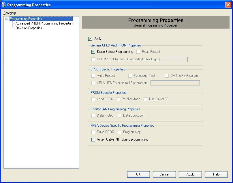
"Programming Properties" window
iMPACT will first erase the SPI Flash memory (notice the mismatch between the two progress indicators)

Erase the SPI Flash memory
and then write the bitsream in the SPI Flash Memory (notice the match between the two progress indicators).

Write the bitsream in the SPI Flash Memory
After successful programming, you should read the message "Program Succeeded" popping up for a few seconds in the "Direct SPI Configuration" panel.

"Program Succeeded"
Move Master Reset switch back to the "Run" position. Make sure that reset swith is disabled:
- S2 is switched to "Run" (ON) after programming (TE0300 module);
- S1D is switched to "Rin" (OFF) after programming (TE0320 module).
In case you uploaded the test design, you should see the on-board led blinking at 0.5 Hz.
Overview
Content Tools